|
LED Voice Flasher |
|
This circuit is commonly called MUSIC COLOUR as the LEDs flash and blink in time with the music. It uses two transistors to amplify the signal from the microphone to drive the LEDs. It will operate from 3v to 5v. Do not use a voltage above 5v as the output does not have a current-limiting resistor and the LEDs will be destroyed. Principle of Operation The signal from the microphone is about 20mV and the current is less than 1mA. The LEDs require a signal of 4v and at least 100mA to produce a bright flash. The two transistors amplify both the voltage and current to achieve this requirement. The first transistor increases the voltage but this is not an important factor as most of the voltage amplification takes place with the second transistor. The first transistor accepts the current from the microphone and when combined with the current from the 1M base resistor, the transistor turns ON more and turns OFF slightly (due to the waveform). This action is passed to the second transistor where the 10k resistor turns the transistor ON and the first transistor turns the second transistor OFF slightly by robbing the base of current from the 10k resistor. The 10k resistor allows a maximum of 0.5mA to flow into the base of the second transistor and if this transistor has a gain of 200, the collector-emitter current will be 100mA. This current flows through the 5 LEDs and is shared equally to pass about 20mA through each LED. We are using the transistor and 10k as "current-limiting" and that's why the supply must not be increased above 5v. The Circuit
The video shows
the LEDs flashing in time with voice and music.
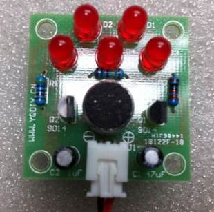
The photo above
shows all the components fitted to the board. The
flat on the side of the LED identifies the cathode lead (the short lead is
the cathode). The placement of the two electrolytics must be observed. The
3 resistors are 4k7, 1M and 10k. You can buy this kit for about $3.50 post-free
21-7-2013 |