|
PROJECTS |
More Model Railway projects:
| FLASHING
RAILROAD LIGHTS This circuit flashes two red LEDs for a model railway crossing.   |
| TRAFFIC LIGHTS
Here's a clever circuit using two 555's to produce a set of traffic lights for a model layout. The animation shows the lighting sequence and this follows the Australian-standard. The red LED has an equal on-off period and when it is off, the first 555 delivers power to the second 555. This illuminates the Green LED and then the second 555 changes state to turn off the Green LED and turn on the Orange LED for a short period of time before the first 555 changes state to turn off the second 555 and turn on the red LED. A supply voltage of 9v to 12v is needed because the second 555 receives a supply of about 2v less than rail. This circuit also shows how to connect LEDs high and low to a 555 and also turn off the 555 by controlling the supply to pin 8. Connecting the LEDs high and low to pin 3 will not work and since pin 7 is in phase with pin 3, it can be used to advantage in this design.
Both 555's are wired as oscillators in astable mode and will oscillate ALL THE TIME when they are turned ON. But the second 555 is not turned on all the time! The first 555 turns on and the 100u is not charged. This makes output pin 3 HIGH and the red LED is not illuminated. However the output feeds the second 555 and it turns on. Output pin 3 of the second 555 turns on the green LED and the second 100u charges to 2/3 rail voltage and causes the 555 to change states. The green LED goes off and the orange LED turns on. The second 100u starts to discharge, but the first 100u is charging via a 100k and after the orange LED has been on for a short period of time, the first 555 changes state and pin 3 goes LOW. This turns on the red LED and turns off the second 555. The first 100u starts to discharge via the 100k and eventually it changes state to start the cycle again. The secret of the timing is the long cycle-time of the first 555 due to the 100k and the short cycle due to the 47k on the second 555. |
| 4 WAY TRAFFIC
LIGHTS This circuit produces traffic lights for a "4-way" intersection. The seemingly complex wiring to illuminate the lights is shown to be very simple.  |
| MODEL RAILWAY
TIME Here is a circuit that will convert any clock mechanism into Model Railway Time. For those who enjoy model railways, the ultimate is to have a fast clock to match the scale of the layout. This circuit will appear to "make time fly" by turning the seconds hand once every 6 seconds. The timing can be adjusted by changing the 47k. The electronics in the clock is disconnected from the coil and the circuit drives the coil directly. The circuit takes a lot more current than the original clock (1,000 times more) but this is one way to do the job without a sophisticated chip.  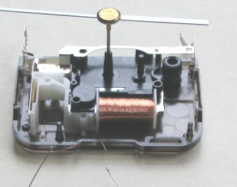 |
| REVERSING A MOTOR-4
(see 1, 2, 3 in 200 Transistor Circuits) In this example the power is applied via the start switch and the train moves to the away limit switch and stops. The 555 creates a delay of 1 minute and the train moves to the home limit and stops. Turn the power on-off to restart the action.
|
25/3/2012