The drive-current for each output line
Each output line of a PIC12c508A can deliver a maximum of 25mA while the PIC16F84 microcontroller can deliver a maximum of 20mA and sink 25mA. We have allowed a maximum of 25mA for all states to keep things simple.
What does this mean?
It means any device connected to an output must take 25mA or less.
If it takes more than 25mA a buffer transistor (also called a current
amplifying transistor) must be added and this will be discussed in a moment.
However, there is another way to limit the current - with the addition of a
current-limiting resistor.
A typical device that requires a current-limiting resistor is a LED. A LED must be supplied with
25mA or less for
it to operate correctly. But you cannot connect it directly to the output of a
microcontroller.
This may seem a contradiction, because the output current of a microcontroller
is 25mA and a LED requires 25mA.
The technical point is this: The output line of a microcontroller is capable of
delivering more than 25mA and a LED is capable of taking more than 25mA and if
the two are directly connected together, one of the driver transistors in the
chip will be damaged.
To limit the current to 25mA, a resistor must be connected in series with the
LED. This is called a current-limiting resistor. Working out the value of the
current-limiting resistor requires some mathematics but this is very easy when you know
how.
25mA
The current taken by a device is called the LOAD CURRENT. Twenty-five milli-amps is not very much in electrical terms but in electronic terms, it is amazing what can be driven. 25mA is 0.025Amp and this is not sufficient to drive a motor or globe but there are a number of devices that can be driven:
1. LEDs (Light Emitting Diodes) require up to about 25mA for
full illumination.
2. Piezo diaphragms require very little current and can be
driven directly from an output line.
3. Low-current relays can be driven directly provided they
operate on 25mA @ 5v. If more than 25mA is required, a driver transistor
(also called a buffer transistor or buffer stage) will be needed.
The specification for a PIC microcontroller output line is 25mA @ 5v. In other words the output line has an output voltage of 5v and the maximum current that can be delivered by it is 25mA. The output line will, in theory, deliver more than 25mA but the transistor in the chip may be damaged (overheated) if a higher current flows. The current delivered by the output line is determined by the resistance of the device (or devices), connected to the line. The simplest device is a resistor as shown in fig: 1.
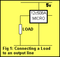
If the value of the resistor is too low, more than 25mA will flow. If the resistance is high, less
than 25mA will flow. The current flow is not determined by the chip but by the value of the resistor. The resistor is called the LOAD RESISTOR or simply the LOAD.THE VALUE OF THE LOAD RESISTOR
The resistance of the load resistor is worked out using Ohm's Law. We know the voltage on the line is 5v. This is V in the formula. The max current available is 0.025A = I in the formula. Ohms Law states: I = V/R (Current equals volts divided by resistance). This equation can be re-arranged as:
R = V/I
Putting the two values into the equation produces:
R = 5/.025
= 200
= 200ohms.
A 200 ohm resistor connected to an output line will allow 25mA to flow when the output is HIGH. This is only a theoretical explanation as a resistor on an output line will not perform any function! It won't do anything by itself except get slightly warm. But a resistor will perform more than 20 different functions, depending on where it is placed in a circuit and the value of the components around it. In our first example below, a resistor is added in series with a LED so that the LED will take a maximum of 25mA. The purpose of the resistor is two-fold. Firstly it allows the LED to create a characteristic voltage across it of 1.7v (for a red LED) and secondly it has a value so that 25mA flows through the LED. The resistor will have 5v on one end and 1.7v on the other. These voltages are provided by the chip and the LED and the resistor has nothing to do with creating them. The resistor simply allows a certain amount of current to flow, depending on its value, and that's the value is worked out above.
A point to note: The '508A has 5 output lines and if all the
outputs are delivering 25mA, the total output for the chip will be
125mA. This is slightly above the allowable maximum current of 100mA
for the chip but will not be a problem.
The PIC16F84 has a maximum of 150mA for the chip and thus only 6 lines can be
delivering current at any one time.
Let's go to a practical situation:
CONNECTING A LED
If a LED is connected to one of the outputs as shown in fig: 2,
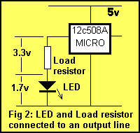
a voltage is dropped across it according to the colour of the LED. This is called the CHARACTERISTIC voltage or the characteristic voltage drop of the LED. This voltage is content, no matter how bright the LED is illuminated. This is completely different to the characteristics of a globe and that's why LEDs and globes must be treated differently when working out their operating requirements.
For a red LED the "characteristic voltage" is 1.7v. For an orange LED the "characteristic voltage" is 1.9v. For a green LED the "characteristic voltage" is 2.1v. LEDs cannot be connected directly to the output of a drive-line without a voltage-dropping resistor. The reason is very technical but basically a red LED, for example, does not turn on at all until exactly 1.7v is placed across it and if the voltage tries to rise above 1.7v, the LED will glow brighter, allow a very high current to flow and will be damaged when the current flow is greater than 40mA.
It is virtually impossible to provide a constant 1.7v and the simplest way to prevent damaging the LED is to connect a resistor in series. If the value of the resistor is worked out via a formula, an accurate current can be delivered to the LED and everything will be ok. The LED will last 100 years or more!
Suppose we want to deliver 25mA to a LED.
If we take a red LED, the value of resistance can be worked out by Ohms
law. The voltage across the resistor is determined by:
5v - 1.7v = 3.3v (The voltage across the LED is the 5v supply
voltage minus the 1.7v dropped across the LED due to the characteristic
voltage drop mentioned above). This is the value for V.
I = V/R
0.025 = 3.3/R
R = 132 Use 130 ohm resistor.
An orange LED has a higher characteristic voltage of 1.9v and thus a lower value dropper-resistor will be required for 25mA. Use 120R.
For a green LED, use 100R. High-bright LEDs are available in all colours and although they are rated at 25mA, they will produce very good brightness at 5mA to 15mA.
For battery operated projects, LED current can be reduced to as low as 1mA, and this will increase the life of the battery enormously.
Table 1 gives the value for the dropper resistor for a red LED
at different currents.
The easiest way to determine the value of resistance for a dropper resistor is
to put a LED in series with a 1k resistor on a 5v supply. Gradually reduce the
resistance until a satisfactory brightness is obtained.
The illumination of a LED is given in milli-candella (mcd) and as manufacturing
has improved over the past few years, the output brightness has risen
considerably. Thatís why itís best to experiment with different value
resistors and come up with a value for your particular LED(s).
|
Dropper resistor for a red LED for a 5v supply: |
|
|
25mA |
130 ohms |
|
15mA |
220 ohms |
|
10mA |
330 ohms |
|
5mA |
680 ohms |
|
1mA |
3k3 |
|
Table 1. Dropper resistor values |
|
CONNECTING A PIEZO DIAPHRAGM
Piezo buzzers, piezo sounders and piezo sirens have active components inside the housing (transistors, choke, etc) to create a very loud sound. These devices operate from a DC supply (6v to 12v).
A piezo diaphragm requires a sine wave or square wave - in other words a "pulsing" waveform to cause the diaphragm to "dish" (bend) and thus produce the characteristic annoying sound. The amplitude of the waveform determines the loudness of the sound and the frequency of the waveform determines the tone.
DRIVING HIGH CURRENT LOADS
Loads requiring more than 25mA must be connected to an output of a microcontroller via a buffer (driver) transistor. A buffer transistor is actually a current amplifier. Transistors can be grouped into low, medium and high current devices.
If a load requires say 100mA, a low-current buffer transistor will be
required.
If a load requires 500mA to 1A, a medium-current transistor will be
required. For currents above 1A, a high-current transistor will be required.
For 100mA, a low-current type such as BC 547, 2N 3904 or BC 338 will
be suitable. If we assume the transistor has a current-gain of 100, 1mA will be
needed by the base for the transistor to deliver 100mA.
You don't get something for nothing. For a transistor to be able to DELIVER
a current to a LOAD, it requires a current to be DELIVERED to it - to the base.
That's why a transistor is called a current amplifying device.
If the transistor is driving a globe, the start-up current for the filament
of the globe is about 6 times the illuminating current and thus the transistor
should be capable of delivering 600mA.
To deliver 600mA, the base must be supplied with at least 6mA. To deliver
this current into the base, the value of the base-resistor can be worked out as
follows:
The voltage across the base resistor will be: 5v (the output of the '508A) minus the base-emitter voltage of the driver transistor (0.7v) = 5 - 0.7 = 4.3v
Resistance of base resistor:
= V/I
= 4.3/.006
= 700
R = 700 ohms.
Use 680 ohms.
This is the maximum value of resistance you should use. (Remember: as the value of a resistor gets higher, LESS current will flow through it.)
In theory a 680R resistor will fully saturate the transistor and provide 600mA to turn on the globe. But suppose the transistor does not have a gain of 100. It may only have a gain of 80 when delivering a high current. In this case the full 600mA will not flow and under the worst conditions the lamp will not illuminate.
To account for this possibility, the base resistor can be reduced so that a slightly higher current will flow into the transistor. In this way you are guaranteeing the transistor will be saturated, just in case the gain is not 100. It's nice to add a margin of guarantee and thus a resistor as low as 470R can be used.
A resistor as low as 470 ohm will not damage the transistor and will not make the globe glow "too bright." It's simply a value to make sure the transistor turns on fully under the worst conditions. If the transistor does not turn on fully, it will get hotter than normal and the globe will be dull. This can overheat the transistor and cause damage - that's why it's important to FULLY turn it on.
A high start-up current is one of the hidden problems with driving globes and is generally not encountered until a high current globe is employed or a number of globes are driven at the same time. As you can see, current is required from the output of the microcontroller to drive the transistor and if high current loads are driven, very soon the 25mA from the micro will be used up!
Suppose you require to drive a 12v 1amp car lamp. A high-power driver transistor will be required as the start-up current will be about 6 amps.
High-current transistors have a current-gain of only about 20 to 50 and if you use the worst-case scenario, the current required by the base to fully saturate (turn-on) the transistor will be 5,000/20 =250mA.
Obviously this is above the output capability of the microcontroller. So you have to carry out some calculations before connecting high-current devices.
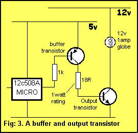
The answer is to add an extra amplifying transistor between the chip and the power transistor as shown in fig: 3. This transistor is called a buffer transistor and effectively amplifies the capability of the chip by a factor of about 100. If the output transistor (the power transistor) requires a current of 250mA into its base, the buffer transistor will deliver this current and require 250/100 = 2.5mA from
the microprocessor. The 2.5mA can easily be supplied by the micro and we are back in business.
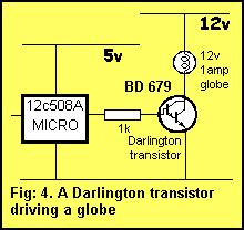
The driver and output transistor can come in two different arrangements. Fig: 3 shows two individual transistors or a single Darlington transistor as shown in fig: 4.
The end-result is exactly the same. The only difference is the number of components required and board space needed.
In fig: 3, when the output of the micro is LOW, the PNP buffer transistor is turned on. This delivers current to the base of the output transistor via a 18R resistor. We have determined the base current must be 250mA to reliably turn on the 12v 1amp lamp. This current must flow through the 18R resistor and the wattage dissipated by this resistor will be surprising! It needs to be 1watt! This is wasted current as it does not perform any function and the 250mA will put a heavy load on the 5v supply. The solution is to put a Darlington transistor in the output as shown in fig: 4.
A Darlington transistor is two transistors in the one case and it looks like a normal transistor with three leads. A typical Darlington transistor can have a gain of 2,500 and if the lamp requires 6 amp at turn-on, the current required into the base will be 2.5mA. The 1k separating resistor will deliver about 3.5mA, remembering there is a 1.2v volt drop between base and negative rail for the Darlington transistor.
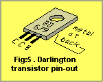
But the biggest advantage of the Darlington design is the absence of the 18 ohm resistor. This will remove the heavy demand on the 5v supply. A suitable Darlington transistor for up to 4 Amp load is BD 679. The pin-out for a BD 679 is shown in fig: 5.
DRIVING TRIACS
If heavy AC loads are required to be driven, a TRIAC can be used as shown in fig: 6.
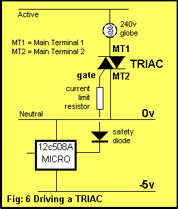
A TRIAC is especially suited to driving AC loads as it will conduct in either direction and can be turned on part-way through a cycle (each half-cycle) to provide dimming for lamps or speed control for motors. TRIACs are available in "sensitive gate" versions requiring low current on the gate. This is ideal for the '508A micro. TRIACs require the least GATE TRIGGER CURRENT when the gate current is negative.
To Top