|
BASIC
ELECTRONICS COURSE
Page 3

Question 35: Electricity (current) passes through a
resistor, but does electricity pass through a capacitor?
Ans: No this is one of the
most important differences between a resistor and a capacitor. We saw how a
capacitor charges when it is connected to a supply rail (voltage rail) and it
appears that the current will pass through it. But this is not the case. Current
flows at the beginning, when the capacitor is discharged and gradually reduces
to zero when it is fully charged. It is like a rechargeable battery. When it is
charged it has a voltage that opposes the supply voltage and thus no
"charging current" flows.
This is a difficult point to comprehend and the animation below shows current
flows when the switch is closed (the LED illuminates) but as the capacitor
charges up, the LED gets dim and finally goes out.
SOME
BACKGROUND FACTS
The 9v battery shown in the examples above delivers
a voltage of nine volts. This voltage is said to be a "DC voltage."
The letters DC stand for "Direct Current." I know this is confusing,
so we just say "DC." It is called "Direct Current" because
it goes back to the birth of electricity when names had to be given to the two
different types of "electricity." One type was constant (direct) and
the other was alternating. The constant voltage had positive appearing on one
wire and negative on the other, and they called it DC. The other had the
positive and negative swapping back and forth, from one wire to the other, very
quickly and they called it AC (for alternating current).
In these questions, we are dealing with a DC voltage and showing how a capacitor
blocks DC. This isn't hard to visualise as a capacitor consists of two plates
(as shown in the circuit diagram) that are separated with an insulating material
(air or plastic). Electricity cannot pass through the insulating material and
that's why DC voltages don't flow through a capacitor.
In the animation below, the LED comes on very briefly when the switch is closed
to show the capacitor is charging. But after the initial charge, the LED does
not illuminate.

Question 36: In the animation above, what
are the "+" and "-" symbols between the plates of the
capacitor?
Ans: These symbols represent
the capacitor charging. Electricity (current) flows into the capacitor during
the charging process and and it is important to realise the capacitor takes time
to charge. It does not charge instantly. The LED turns on during the charging
time and once the capacitor is charged, NO current flows in the circuit.
Question 37: What are the values of capacitance for
electronic circuits?
Ans: Electronic circuits use a
wide range of values and the only way to explain the range is to start from the
beginning.
The basic value of capacitance is the FARAD.
The Farad is a very large value and a more useful value for electronic work is
one-millionth of a Farad called a microfarad. It is written uF and sounded as
"mu-eff."
One microfarad is further divided into one million parts to make the smallest
capacitor we will be dealing with. It is called a pF capacitor (sounded as
"pee-eff" or simply "pee") and is one picofarad. It is
one-million-millionth of a farad. But don't worry about the complexity of this
value as we will be simplifying the whole range in a moment.
It is commonly referred to as "puff" to get away from saying
"pee!"
Finally, there is one more value in the range of capacitors used in electronics.
It is "nano." One nanofarad is equal to 1,000
picofarads.
Question 38: How can the range of capacitor values
be simplified for a beginner?
Ans: The best way to think of
capacitors is to treat the microfarad as the central or centre value in the
range, as you can get values 100,000 times greater and smaller than this value.
Values higher than 1 microfarad are easy to understand as they are simply 10uF,
100uF, 1,000uF or 100,000uF.
Values smaller than 1uF are easy to understand if you remember the following:
1,000pF = 1 nanofarad
1,000 nanofarad = 1 microfarad
More about capacitor values later.
Question 39: Can capacitors be connected in
parallel?
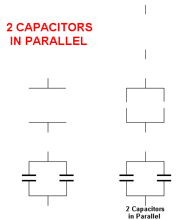
Ans: Yes. The following
animation shows two capacitors connected in parallel:
Question 40: Can capacitors be connected in series?
Ans: Yes. The following
animation shows two capacitors connected in series:

Question 41: Why do you connect capacitors in
parallel and series?
Ans: 1. To create
"special" values of capacitance.
2. To get a higher voltage rating (this
will be discussed later).
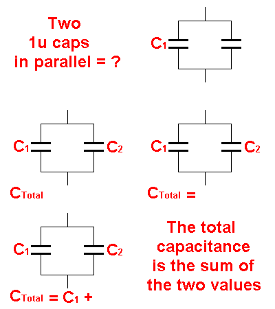
Question 42: What is the value of two 1uF
capacitors connected in parallel?
Ans: The following animation
gives the answer:
Question 44: What is the value of two 22u capacitors
connected in parallel?

Question 45: What is the value of 100u and 220u
connected in parallel?

Question 46: What is the value of two
capacitors connected in series?
Ans: The mathematics for this
is quite complex and will be covered later. The only thing we can say at this
stage is the result of connecting two EQUAL value capacitors in series is half
the value of one of them. For example: Two 100u capacitors connected in
series results in a value of 50u.
THE
DIODE
The diode is a device (a passive device) capable of
conducting in ONLY ONE DIRECTION. It's exactly like the Light Emitting Diode
covered above except it does not give off light when current passes through it.
In a question above we saw the LED does not illuminate when placed around the
wrong way in a circuit. This is the same with a diode. It only conducts when the
anode lead is connected to a higher voltage than the cathode lead.
There is one
more thing you need to remember: when a current is flowing through a diode, a
"voltage drop" of approx 0.7v appears across it. This is a
"characteristic voltage" and does not change from one diode to another
nor does it change due to increasing or decreasing current flow or the rail voltage on which the
diode is placed. It's very similar to the "characteristic voltage" of
1.7v for the red LED discussed above. It is best to think of the leads as
"anode lead" and "cathode lead" as the words
"anode" and "cathode" have a slightly different meaning when
it comes to chemistry and electrochemical reactions.

The animation below shows that a diode conducts in
only one direction. This is due to the semiconductor material inside the diode allowing electricity to flow in
only one direction. The arrow symbol on the diode shows which way the
current will flow as the convention is: ELECTRICITY FLOWS FROM POSITIVE TO
NEGATIVE. This is called CONVENTIONAL CURRENT FLOW.

Question 47:What is a
"REVERSE BIASED DIODE?"
Ans: A diode in reverse is called a REVERSE BIASED DIODE and sometimes a diode
is placed in reverse to prevent current flowing. A diode can also be placed in
a circuit so that only a battery connected around the correct way will operate
the circuit. The diode will prevent current flowing if a battery is connected
around the wrong way. A very simple but valuable "trick" to remember.
Question 48: How can
you identify the cathode lead of a diode?
Ans: The cathode lead is always identified by a ring or mark around the body of
the diode. This ring is at the end of the body near the cathode lead. It is the
cathode lead that we talk about (and identify) when dealing with diodes. The
small letter "k" is also used in some circuit diagrams to identify
the cathode lead.
Question 49: Why are
there large and small diodes?
Ans: Diodes range in size due to their current handing capability. A larger
diode is capable of handing more current. The size of the leads is also an
indication of the current handling ability as a diode gets hot when a current
flows through it and the leads remove the heat from the centre of the diode to
the outside. This is called dissipation.
Question 50: Draw the symbol for a diode:

Question 51: What is the voltage drop across a
diode:

TEST:
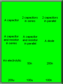
Drag the components to
the correct position on the map.
Click to release:
The components we have
studied so far are called passive components. In other words they do not
amplify. There are lots of circuits you can build with passive components and
they are called ELECTRICAL CIRCUITS. But this course is aimed at
electronic circuits and the first active component we will cover is the
TRANSISTOR. It is called an active component because it is capable of
AMPLIFYING. But just before we do, there are a couple of very important
fundamentals in waveforms we need to cover. On the next page you will get a very
good understanding on how a waveform is produced and how we represent it on a
graph.
By increasing and decreasing a voltage in a gliding manner, a very special
waveform is produced called a sine wave. Not every rising-and-falling
voltage produces a perfect sinewave but they do produce waveforms that look like
a sinewave.
Speech consists of rising a falling voltages and at this point in the course we
are not interested in the pattern produced but the fact that the rising and
falling voltage is called an "AC voltage." This is where we
start to bring things together.
We mentioned that capacitors do not pass DC but they pass AC and thus the
capacitor we studied earlier will come in to our discussion. Secondly, the next
component, the transistor is perfectly suited to amplifying AC signals and we
will see how this is done.

| 