|
|
BASIC
ELECTRONICS COURSE
Page 40  INDEX
INDEX

TEST 5
This
test is along the same lines as test 4. If you did not do very well in the
previous test, now is the time to go over the pages of the course and
study the the information again.
You should really be looking at 100% success rate as electronics is a
perfect science. If a circuit is not 100%operational, it will not work.
That's the beauty of electronics. It pulls you up all the time. A circuit
must be 100% correct for it to work. And that's why you should be able to
answer all the items we are covering in this test.
Don't do this test until you have brushed-up on your theory.
|
Question 1: What is the value of a resistor with the following colour bands:
brown-black-green-gold:
| |
|
|
Question 2: What
are the colour bands for a 47R 5% resistor:
| |
|
|
Question 3: Draw
a 33k and 220k in series (include colour bands). What is the
combined resistance:
Draw
a 33k and 220k in series (include colour bands). What is the
combined resistance:
| |
|
|
Question 4: Name
a reason why resistors are connected in parallel:
Name
a reason why resistors are connected in parallel:
| |
|
|
Question 5: Draw
an NPN transistor in EMITTER-FOLLOWER mode, with a LOAD resistor:
| |
|
|
Question 6: Draw
a 100n capacitor in series with 10n:
| |
|
|
Question 7: Why
are capacitors connected in series:
| |
|
|
Question 8: What
is the value of 100n connected in series with 100n:
| |
|
|
Question 9: Draw
an NPN COMMON-EMITTER stage with 1M base-bias resistor, 2k2 LOAD resistor, 10n
input capacitor and 100n output capacitor:
| |
|
|
Question 10: Draw
a flashing LED connected to a 5v supply:
| |
|
|
Question 11: Draw
an NPN common-emitter transistor driving a LED:
| |
|
|
Question 12: Draw
the NOT gate and determine the output when the input is HIGH:
| |
|
|
Question 13: Draw
the NOR gate and determine the output when both inputs are HIGH:
| |
|
|
Question 14: What
is another name for the NOT gate?
| |
|
|
Question 15: Draw
a single-input Schmitt Trigger Inverter driving a single-input Schmitt Trigger
inverter: What is the output when the input is LOW?
| |
|
|
Question 16: Draw
a Schmitt Trigger oscillator driving a single-input Schmitt Trigger Inverter,
with this inverter driving a LED:
| |
|
Question 17: Draw
a Low-frequency Schmitt Trigger oscillator gating a High-frequency
Schmitt Trigger oscillator,
with the diode "gating" (jamming) the second oscillator when the first
oscillator is LOW :
| |
|
|
Question 18: From
question 17, what determines the number of flashes produced by the LED?
| |
|
|
Question 19:
If the input voltage on a
Schmitt trigger is changed from 40% rail voltage to 60% rail voltage, then
back to 40% rail voltage, what happens to the output?
| |
|
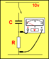
Question 20:
What is the voltmeter detecting?
|
|
|
Question 21: Connect
the piezo diaphragm to the transistor so that small vibrations detected by the
piezo, will be amplified:

|
|
|
Question 22: In
question 21, why don't we need an input capacitor on the base, (between the
piezo and base)?
| |
|
Question 23: When
two transistors are connected together with capacitors,
the circuit is said to be: (a) AC coupled
(b) DC coupled
| |
|
Question 24: In
question 23 above, what do the letters AC stand for?
Question 25: A
High voltage is present in a circuit. Does that also mean a high current is
present?
| |
|
NEXT

|