
|

The
Transformer
All you need to know about
the transformer. . .

INDEX
Page 54
The symbol for a power transformer can be any of the
following:
 The
number of loops in the symbol does not indicate the relative size of the winding
however it is handy to show some sort of comparison so that you can see what
the transformer is doing.
The only reason why the secondary may be drawn larger than the primary is
to fit in with the other symbols on the circuit diagram.
The animation below shows the "Mains" entering the primary of a
transformer and the resulting waveform on the secondary. The shape of the mains
voltage is called a sinewave and the output will reproduce this shape and have
an amplitude according to the ratio of the turns on the primary to the
secondary. 
As more turns are added to the secondary, the voltage
increases. If
the turns on the secondary is less than the primary, it is called a STEP-DOWN
transformer. If the secondary has more turns than the primary, it is called a
STEP-UP transformer. If the turns are equal it is called an ISOLATING
transformer.
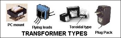
TYPES OF TRANSFORMER
There are thousands of different types, styles and sizes of transformers on the
market. The diagram below shows some of the types we are covering in this discussion:
USES
A transformer can provide more than 30 different features in a circuit, and sometimes it is
providing 3 or more at the same time.
Here are some of the features it can provide:
1. Isolating one voltage from another,
2. Increasing the voltage,
3. Decreasing the voltage,
4. Increasing the current,
5. Decreasing the current,
6. Providing a phase reversal,
7. Providing a phase shift,
8. Providing a feedback voltage or pulse,
9. Electromagnetic radiator,
10. Electromagnetic detection,
Plus a lot of effects when combined with other components, such as:
oscillators, filters, signal boost, signal attenuation and lots more.
The diagram below is a simple transformer wound on a soft-iron or ferrite core.
If AC is applied to the primary, a voltage will appear on the secondary. This
type of transformer is not as efficient as one with a "complete magnetic
path" - however it does work. 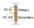
If
the magnetic path is complete as shown in the diagram below, more energy is
transferred from the primary to the secondary, via the magnetic flux. The
magnetic flux moves clockwise (it is called EXPANDING FLUX) during the
first half of the cycle and in a counter-clockwise direction (called DECREASING
or COLLAPSING FLUX) during the second half of the cycle. 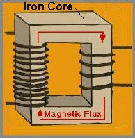
THE
POWER SUPPLY TRANSFORMER
In this section we will discuss the transformer in its role as a POWER TRANSFORMER in a POWER SUPPLY.
The transformer
plays a very important part in producing a successful power supply but it is a component we
tend to know
very little about.
Very few specifications are provided with a transformer and quite often these are over-rated.
There are a number of specifications you need to know when using a
transformer and the only way to find them out is to build an experimental
circuit. A transformer works very well until you need to use its full output.
That's when you find things go wrong.
Take for instance, current rating. How many times have you seen two different
transformers. One is larger than the other but they are both rated 12v @ 500mA.
There are a number of reasons why this can be true - or seemingly true.
It's all in the way you test the device. No matter how you see it, it's always best to
go for the larger transformer. There is no way a manufacturer can
put extra "power" or "punch" into a smaller unit and
get a "boosted" output - unless the transformer is different design.
The 500mA rating for the smaller transformer
may be for a very short period of time or the transformer may have a slightly higher
output voltage so that when the full 500mA is drawn, the output voltage will
fall to the specified value.
The main problem with this is the higher voltage is passed to the input of your
power supply and must be dissipated in the regulator as "wasted
heat." This reduces the efficiency of the power supply because the
regulator is already getting very warm and when a higher current is required,
the regulator may shut down. In addition, the transformer runs very hot because
it is delivering more voltage (and thus more wattage) than needed.
This is an extreme example but is exactly what happens in reality.
The smaller transformer is said to have POOR REGULATION and is not the best
type to use.
Obviously the best type is one that is slightly larger than
required so that it runs cool.
Again, all the mathematics in the world will not beat the simple task of
feeling the transformer after it has been operating for 30 minutes or so.
Again, there are two checks to be made. Check the transformer after 30 minutes
of no load and again after 30 minutes of full load. What could be simpler. I
could provide you with a 2-year course on transformer-design, or a 10 second
test to check the temperature. Basically, if the transformer is getting too hot
on no-load, the flux density in the core is too high. It works like this: As
the input voltage rises, the primary turns produce a magnetic field and this
field passes through the magnetic material in the centre of the coil, called
the CORE. The field turns "little magnetic dipoles" in the core and aligns
them in a particular direction. These magnetic dipoles then have the effect of
producing a magnetic field in the opposite direction to produce a reverse
voltage that is almost the same magnitude as the incoming voltage.
If the incoming voltage is 130v, at a particular instant, the voltage produced
by the transformer may be 125v and thus the forward voltage is really only 5v.
This is an amazing situation but is exactly what happens. For this to occur you
don't need any secondary winding. It can be removed and exactly the
same result will occur.
Now we come to the reason why some transformers get hotter than others.
There are two reasons.
The material in the core is iron (called soft iron) and this is a conductor of electricity. As the
magnetic flux passes through the core, it is not absolutely uniform and any
non-uniformity allows a small voltage to develop from one area to the other and
this voltage causes current to flow. The core material is sliced into thin
sheets called laminations to create a very long path and thus a high resistance
is created so that the actual current flow is as small as possible. However a small
current does flow and this causes some warming of the core.
But the major warming comes from the primary winding.
As the primary voltage increases, more and more magnetic dipoles align in a
direction to produce a reverse or "back" voltage. But there comes a
time when there is no more magnetic dipoles, and the reverse voltage does not
keep up with the incoming voltage. The difference between the two voltages
increases and thus by simple Ohm's Law, the primary current increases due the
resistance of the primary winding. This increased current only occurs during the peak of each waveform
and that's how the transformer gradually warms up - the primary winding gets
hotter and passes its heat to the core.
When a load is applied to the transformer, the magnetic flux produced by the
primary winding cuts the turns of the secondary and induces a voltage in each
turn. This
voltage is the "pressure" that allows a current to flow in the
secondary circuit. The magnetic flux is passed to the secondary winding and does
not have time to activate as many magnetic dipoles. Thus the "back"
voltage is not as high and more current flows in the primary winding. If we
take more current from the secondary, the primary draws more current from the
"mains."
DESIGNING
A TRANSFORMER
We are not going into the design of a transformer as this is
beyond the scope of
this discussion. There are plenty of transformers on the market to choose from
and you cannot build one cheaper than the ready-made item.
WHAT'S THE
ADVANTAGE OF A CENTRE-TAP?
There is basically two
types of output windings. One is a single winding and the other is tapped.
Before we discuss the advantages of the single winding, we need to go into some
theory.
The most efficient transformer has half the bobbin wound with the primary
winding and half with the secondary. This allows the largest gauge wire to used
for each winding and thus the "copper losses" are the least.
"Copper loss" is the heat generated in the winding due to current
flow. A winding delivering 1 amp gets much hotter than an ordinary piece of wire
carrying 1 amp because the winding is GENERATING the current and lots of
"eddy currents'" are flowing in the wire. These can be thought of as
currents flowing is the wrong direction, but eventually enough current flows in
the right direction to create 1 amp. If the wire is thick, the resistance of the
wire is low and it does not get as hot as thinner wire.
Now we come to the comparison of a single secondary connected to a full wave
rectifier (4 diodes) and a centre-tapped secondary connected to 2 diodes.
The diagram below shows
these two arrangements. 
A single secondary winding Vs centre-tapped
secondary
In
the diagram, we are assuming the output is the same in both cases, (such
as 12v @ 1 amp). In the first case, the secondary is delivering current to the load via
diodes b and c in the first half-cycle and via diodes a and d in the second half
of each cycle. This puts a load on the winding of two pulses of energy per
cycle. In addition, there is a drop across two diodes.
In the second case, winding A delivers current to the load via the top diode
during the first half of each cycle and winding B delivers current to the
load via the bottom diode, during the second half of each cycle. Each winding has a
short period of rest-time between pulses of energy.
The question is: Which circuit is the best?
The answer is circuit 1.
The centre-tapped circuit has some advantages but overall, Circuit 1 is the
better choice.
The centre-tapped transformer is basically delivering energy from half the
secondary space on the transformer at each half cycle and thus the
winding is a thinner gauge (to fit in the space) and will get slightly hotter
than the single-secondary. The result is the
centre-tapped transformer has to be "driven harder" to deliver the
same output current as the single secondary transformer.
In the diagram below, the circuit is a combination of a bridge rectifier and a
7805 voltage regulator. Click the pieces and they will change places.
A 7805 1-Amp Power Supply
To unscramble, you need IE 4 or
later.
Click two pieces and they change places.
MOUNTING
There are three ways to mount a transformer.
1. Mounting lugs or tags. The transformer will have either flying leads
or solder tags.
2. Printed Circuit board mounting. The transformer will have pins to go
through holes in the PC board.
3. Toroidal transformers have a mounting screw that goes through the
centre of the transformer and screws to a base-board.
Only mount very small transformers directly onto a PC board - large transformer
will break the trackwork. This form of
mounting is very dangerous as the mains connections are exposed on the underside
of the board. It is also very difficult to fit the board into an enclosure, with a
heavy transformer sitting on one end.
CONCLUSION
The answer is simple. If you are designing a power supply, collect (or buy) a
range of transformers and test them on your project. Feel the temperature after
a period of time and check the current capability by loading each device with
the required current. You can even draw slightly more current during the
"test" to determine if the transformer is operating at its maximum, or
if there is a little extra current in reserve.
Don't take manufacturers specifications as factual. Most specifications are
either "guessed" or exaggerated. It's a bit like the output rating of
a stereo systems. How can an amplifier produce 100watt output if the power
transformer is rated at 12v @3.5 amp?
The size (and weight) of a power transformer is a very close indication of its
VA (Volt-Amp) rating. This is the AC output Voltage multiplied by the output
current (Amps).
Simply get a range of power transformers and note their VA rating.
The VA rating is not a linear scale. In other words, if a transformer is
increased to double the weight, the VA rating can increase by more than double.
This is because larger transformers have a higher efficiency rating.
Note the size of the wire in the secondary. It should be as thick as possible.
Also note the way the transformer is made. It should be "potted" to
prevent the windings and laminations moving and vibrating during operation.
As I said. The answer is simple. Feel the transformer after 30 minutes of operation.
If it "smells" or feels too hot, replace it with a larger design.
See Page 2 for more on the transformer,
including the secret to making a transformer with a very high output current.
NEXT
|