|

The
Voltage
Regulator as a
Constant Current
Device

INDEX
Page 58
The voltage
regulator can be wired to produce a constant output current. This is not
suitable for some applications as many devices require a high current at
start-up (motors and globes) while others require a varying current (amplifiers)
for their operation.
However there are a few devices that need a constant current for their correct
operation and one device is the Laser Diode.
The actual current requirement depends on the output of the diode and a standard
1 milliwatt type requires between 70 and 100 milliamp.
The characteristic voltage developed across the diode is less than 3v so that a
3-terminal regulator that goes down to 1.2v will be needed. HOW
THE CIRCUIT WORKS
By simply connecting a resistor between the output of the regulator and the
load, and taking the common or "adj" terminal as shown below, the
output current can be set by the value of the resistor. 
It
works like this: No current "comes out" the adjust terminal. It is a
"sense" line. It merely acts as the 0v reference line for the
regulator. The only side issue is the current taken by the regulator flows
through the adjust line and this is approximately 10mA. But in our discussion,
this is ignored.
The voltage between the output terminal and "adjust"
is fixed a 1.2v (for this type of regulator). The 18R resistor in the circuit is
called a voltage dropping resistor. It is designed to produce a voltage across
it according to the current flowing.
If it is 18R, the current flow will be: 1.2/18 = 66milliamps. If the resistor is 10R, the
current needed to produce 1.2v across the resistor is: 1.2/10 =
120milliamps. If we choose 15R, the current flow will be 1.2/15 = 80milliamps.
The laser diode in the example above requires a current between 70milliamps and
100 milliamps. You can choose 15R or 18R for the voltage-dropping
resistor.
How the 3-terminal regulator keeps the output current constant, even if
the input voltage is increased:
Firstly, the current through the "common" or "adj" lead is
only about 10mA and this will not come into the discussion.
If the input voltage is increased, the output voltage will (may) increase and
this will allow the load (the laser diode) to take more current. The increased
current through the 15R or 18R resistor will increase the voltage across it ad
this will be detected by the circuit inside the regulator. The circuit will
"turn down" the output voltage and everything will be
stabilised.
This type of circuit is needed to drive a laser diode from a battery supply. As
the voltage drops, the constant-current circuit maintains the same
current.
If the constant-current circuit is not included, the current to the laser diode
would drop as the battery voltage falls and the laser diode would cease to
operate if the current falls below a certain minimum.
All "Laser Pointers" have an inbuilt constant current circuit
to maintain the operation of the laser.
ANOTHER CIRCUIT
Here is another circuit for a constant Current Source. Although the
circuit is correct, it contains a number of items that should be addressed. The
diode bridge should be drawn as a diamond to make it easy to see the four diodes
are acting as a bridge. The 100u should show the positive lead to make it
obvious the capacitor is an electrolytic and the LM317 should be drawn with the
"out" terminal on the right side of the symbol so you can see exactly
how the device is wired. It's things like this that make a circuit quick
and easy to read. 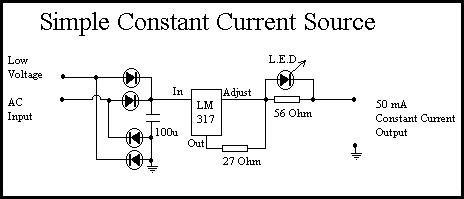
NEXT
|