
|
|
TERMINOLOGY: A coil can be used as a "pick-up" to detect magnetic or metal objects. It can be called a TRANSDUCER, Inductive transducer, magnetic transducer, coil, pick-up, inductor, magnetic coil, pickup coil, inductive loop, inductive sensor, magnetic sensor, metal detector, comparator, gold detector, crack detector - to detect cracks in welds etc, head - as in a tape recorder. |
THE INDUCTOR AS A "PICK-UP."
Now we come to an important feature of a coil when it is used as a SENSOR.
When a magnet passes a coil (this includes the action of moving towards or away from a coil), a voltage is generated in the turns in the form of a sinewave.
We use the term "sinewave" to indicate the approximate shape of the waveform to distinguish it from other shapes such as "square wave," "exponential" or "glitch." A sinewave is a continuing waveshape with a gradual rise and fall as shown in the following example:

The same type of waveform is produced if the magnet passes the end of the coil, into and
out of the end of the coil or if the magnet passes through the centre.
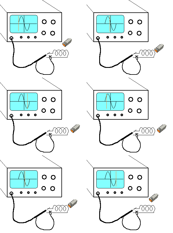
If the magnet is moved rapidly, the amplitude of the waveform INCREASES.
The amplitude is also determined by the strength of the magnet.
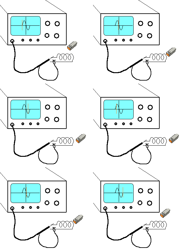
There are three important points to note.
The first is the voltage produced by the coil as it
passes the end of the coil.
When the magnet is directly opposite the end of the coil, the change in
magnetic flux is zero and thus the voltage produced by the coil is zero.
The second point is the change in voltage produced by the coil.
The output voltage changes from positive to negative during the very
small portion of excursion when the magnet moves from a forward to
reverse direction as seen by the end of the coil.
The third point is the coil produces zero voltage when the
magnet is not moving.
If the magnet moves at a faster rate, the voltage produced by the coil
will be greater as shown by the animation below:
If two or more coils are placed in close proximity
with one or more coils providing a magnetic field, when a magnet or metal
object is passed through the filed, the waveform produced by the
sensing coil is altered. The size and shape may be very small but amplifying stages
can produce amazing information.
This is the principle of a metal detector (gold detector) or a coin
detector in a vending machine.
The resulting waveform can discriminate between a coin and a "slug," an aluminium can, a
"pull ring" or a gold nugget.
This type of detector is beyond this discussion. We will only be
discussing how to detect the frequency of the pulses and the amplitude of
the voltage from a single coil.
For an inductive pick-up to be successful, the magnet passing the end of
the coil must be powerful and pass near to the end of the coil.
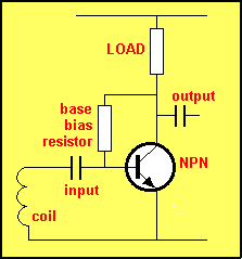
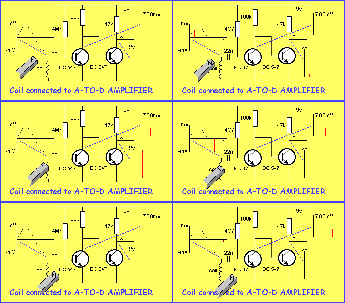
The output of a coil will generally be less than 700mV and must be AC
coupled to a transistor so that the voltage produced by coil will modify
the biasing of the transistor as shown in the diagram below:
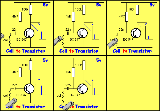
In the diagram below, the magnet is passing the coil and when it is receding from the coil, the voltage produced by the coil turns the transistor OFF and the voltage on the collector rises.
The coil can be connected to a two-transistor arrangement to produce a square-wave output, suitable for circuits that require a noise-free signal:
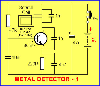
A very simple circuit using a coil is shown in the diagram below. It is
our METAL DETECTOR -1.
It uses a 16 turn coil (approx 6" dia) to detect metal objects such as
coins etc. The circuit oscillates at approx 140kHz and the frequency
produced is picked up by an AM radio to produce a quiet spot on the dial.
When a piece of metal is placed near the coil, the frequency of the
circuit is altered and this is picked up by the radio as a low frequency
tone. The circuit is extremely sensitive and
a shift in frequency of as little as a few hertz will be clearly heard.
ROTATION
A motor is an example of a rotating inductor. Most small motors are 3-pole (the minimum number of poles for self-starting) and if a motor is used as a generator, the output will correspond to the speed of rotation.
For a 3-pole motor, three waveforms are produced for each revolution and the following diagram shows the type of waveform produced:
![]()
If the motor increases in RPM, the waveform changes:
![]()
A detecting circuit can be used to count the pulses and determine the
RPM.
By putting fan blades on the shaft of a motor, you can measure wind
velocity and the output of heating and cooling systems etc.
The output from the motor can be calibrated by placing the fan outside the window of
a car traveling at a known velocity.