|
|
TRICKS
with the
OUTPUT

Page 22
INDEX
Many programmers delight in producing code and sub-routines that require the
minimum number of lines or the minimum number of cycles. This type of code is
so clever,
it can take an hour or more to realise how it works! I have pondered over three
lines of code, for three hours! - before realising how it worked!
There are other passions.
One is to use the minimum number of outputs for a particular application.
This article shows how to use the minimum number outputs to drive a LED display.
LED DICE
The first project we will look at is a LED Dice project. A simple version can
be found in the Projects section: LED
Dice. The circuit uses two chips ( a 555
and a 4017) to illuminate a single dice. It has a tumbling feature to shake-up
the dice and display the result on a set of LEDs. The circuit is very
impressive for a 2-chip design but with the advent of microcontrollers, we can
produce a more-spectacular 2-dice effect, with a single 8-pin chip.
In this discussion we will look at how to interface a set of 14 LEDs to the
output of a PIC12c508A microcontroller.
The animation shows the effect we require:


14 LEDs are driven to produce separate displays of 1,
2, 3, 4, 5, and 6 on the face of a pair of dice.
The smallest microcontroller capable of doing this is the
PIC12C508A.
There are the 4 parameters you have to work with:
1. The PIC12C508A has 5 outputs.
2.Each output is capable of delivering 25mA.
3. A maximum of two LEDs can be placed (in series) on each output.
4. Outputs can be multiplexed (12mA per LED).
These parameters can be expanded by adding driver transistors and gating
components and these options will be investigated.
Other microcontrollers have more output lines but the CURRENT capability is the same. The PIC12C508A is the cheapest
microcontroller for the job.
The first thing to note is the drive capability:
The output of each line will SOURCE 25mA and SINK 25mA.
An output SOURCES a current when it is HIGH.
An output SINKS a current when it is LOW.
The following diagrams show 6 different arrangements for driving one or two LEDs
from a single output.
Resistors are needed to limit the current to 25mA. In circuits 5 and 6, either
the red or green LEDs are on. Both colours cannot be on or off at the same
time. This is one
of the limitations.
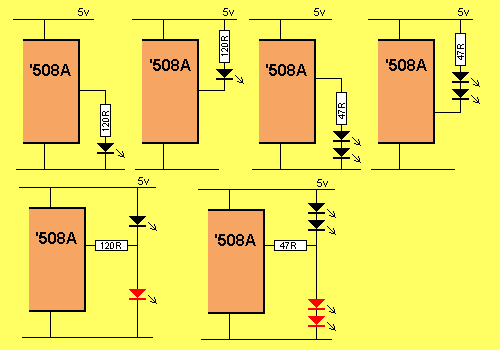
Driving LEDs via a single output
Using the above information we can create a two-dice display. The
diagram below shows two sets of 7 LEDs. The LEDs in grey are not in the
display. They have been included for a different purpose, as explained in a
moment.
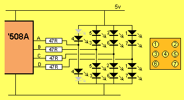
As we have explained above, the LED Dice project has a display showing two separate dice. The
displays "tumble over" and show the numbers 1, 2, 3, 4, 5 or 6. To
drive this number of LEDs would normally take from 8 to 14 outputs. But with a little bit of preliminary
simplification the LEDs can be driven by 4 outputs. Each row contains two LEDs.
The first row contains one LED that is not in the display. It has been included
in the output so that the circuit works properly. We will explain why in a
moment.
Firstly we have to explain how the circuit works. It's very simple. When an
output goes HIGH, the two lower LEDs are illuminated. When it goes LOW, the top
two LEDs are illuminated.
When a output is changed to an input, it has a high impedance and none of the
LEDs are illuminated.
When the display is "static" none of the LEDs will illuminate because
the voltage across each LED must be 1.7v for the LED to illuminate. The voltage
required across 4 LEDs is 6.8v But the supply voltage is only 5v, and
thus none of the LEDs will illuminate.
This is the first trick we have used.
The second trick is the addition of an extra LED in the first column so that
the same reasoning will apply.
The LEDs merely prevent the centre LEDs in the display illuminating when
the project is at rest.
Now, for the third trick.
It is easy to see that the top LEDs will come on when the outputs are LOW, and
the lower LEDs will illuminate when the outputs are HIGH.
So, how do you create different numbers on the two faces AT THE SAME TIME!
The answer is called MULTIPLEXING.
It's very easy to understand.
When the output is HIGH, some of the outputs are turned on to produce the
number "6." When the outputs are made LOW, some of the lines are
made inputs, and thus some of the LEDs are not activated.
This sequence is repeated very quickly and the result is two different numbers
on the dice.
All the tumbling action and the display-time is created by the program in the
chip and the result is a project with more appeal than the LED Dice design,
but requiring fewer components!
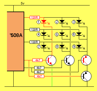
GATING
Gating is another word for CONTROLLING. In the next example we show how to
individually activate 9 LEDs in a display, using 5 lines. The project
using this display is Noughts and Crosses and is one of our future
projects. The animation below shows how each LED is activated. To turn on
a LED, one of the drive lines is taken HIGH and the corresponding sinking
transistor is turned on. This applies to the first two rows.
The third row needs some attention as the two PNP transistors are turned on
when the base of each transistor is LOW. This only occurs when the first two
rows are not activated.
When the first or second row is activate, one of the PNP transistors will be
turned on but the third column of LEDs require BOTH PNP transistors to be
turned on and this means the first two rows need to be off. Study the animation carefully and you will se exactly what is
happening.
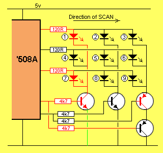
The activation of the display in the Noughts and Crosses project is taken one step further, as shown in the
animation below. All the LEDs cannot be turned on at the same time because the
outputs of the micro are not capable of delivering sufficient current, plus the
arrangement of the circuit will not allow them to be activated at the
same time.
The LEDs are turned on one column at a time. This is called SCANNING and
the direction of the scan is shown on the diagram.
Any or all the LEDs in the first column can be turned on by making the
corresponding output HIGH, then turning on the first transistor. The micro then
turns off the first column and turns on the second column. Finally, the third
column is turned on and off.
Each output is capable of delivering 25mA, and if each LED is turned on for 33%
of the time, the average current is 8mA. This arrangement is called
multiplexing and a LED receiving 8mA in a rapid succession of pulses will
result in a brightness very nearly equal to a LED receiving a constant
25mA.
The diagram below shows the display being scanned and you should be able to see
the letter X being displayed:
More on this topic in future pages.
NEXT
|