|
| ||||||
|
|
PROGRAM MEMORY
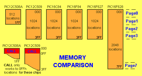
Program Memory is the space available for your PROGRAM.
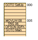
ADDITIONAL NOTES :When the frequency of the oscillator of a PIC microcontroller is 4MHz, it takes 1uS to carry out each instruction. If the instruction causes the micro to go to another part of the program, the instruction takes 2uS. A program can be placed anywhere is memory and to do this there is a pseudo instruction called ORG. ORG is called a pseudo instruction as it is not burnt into the chip but tells the assembler where to burn the first instruction in a program. ORG must have a value associated with it. For instance, ORG 000 will tell the assembler to place the first real instruction in your program at address 000, when the chip is burnt. If you specify ORG 0CC, the following instruction will be placed at memory location 0CC, when the chip is "burnt". You can use ORG again in a program to force a particular sub-routine to reside at a particular location. For example ORG 1AF will force the instruction MOVLW 01 to be at location 1AF in memory: ORG 1AF MOVLW 01 INTERRUPT VECTOR When a microcontroller is operating in a circuit, an event on a input line can trigger the micro to perform a particular operation. This event is called an interrupt and causes the micro to go to location 004 in memory. An instruction is placed at this location to make the micro go to a sub-routine to handle the event. Location 004 is called the Peripheral Interrupt Vector location and since memory starts at 000, we need to start our program below 004 so that location 004 can be used at a later time. The first location in memory is called the RESET Vector. The microcontroller goes to this location during turn-on and whenever a reset is created. At memory location 000, an instruction is needed to take the micro to location 005, for the start of the program. The following instructions show the code:
The program will be burnt into a chip as follows: (actually the binary code will be burnt into the chip).
| |||||


