|
12 DIGIT RUNNING SIGN |
|
|
It's 1970 and a 12 digit LED Display for pocket
calculators has just been released.
Nation Semiconductors are in the forefront of designing miniature
displays for calculators and have a range from 2-digit to 16-digit
displays.
The actual 7-segment displays are so small it takes a bubble magnifier in front
of the LEDs to see the digits. We have used one of these in this
project.
In this project we use one to produce a LED display. It has two features. The characters can be static or "running" and the display can be seen at night.
HOW THE CIRCUIT WORKS
The circuit consists of a number of "Building Blocks."
The main blocks are the LED display, the micro, the 4017 IC and the 5-buttons.
The Display is a 12 digit calculator display, very similar to that shown in the photo:
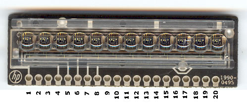
A 12-Digit Display. This one is
from HP. Ours is from
NS and has different pin-outs.
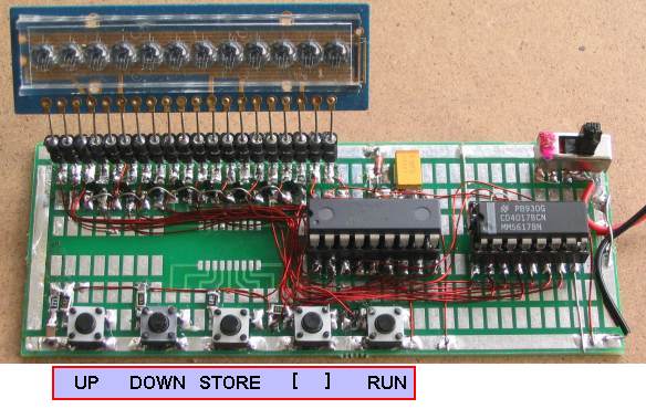
12-Digit Running Sign built on
Surface-Mount Experimenter PC board
(once you start with surface-mount
you never go back to through-hole components)
The [ ] button is for future ideas such as "Count To 10
million."
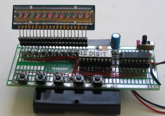
The camera takes a picture of the
segments during the scan process
and the characters are not complete!
The board is designed to take a surface-mount PIC micro or
an 18-pin chip in a socket.
The display is scanned (multiplexed) but not in the normal way.
Normally the segments are accessed and the common cathode for the first
display is turned on to produce a run-of-12 and each display would get
8% of the total time.
In other words the digits are illuminated from left-to-right and this is
done quickly so that they all appear to be lit at the same time.
But we can improve on this by a factor of 50% by connecting all segment A's together,
all B segments together etc and take all the cathodes to 0v
rail via separate lines. In this way we can access the segments via a run-of-eight
and provide 12% illumination for each segment. This will result in a brighter
display.
This is how the display is configured internally and how the display is
intended to be accessed.
In this method of driving the display, only one segment of each digit is
turned on at any time and this means the "common" only requires about
25mA "sinking capability." This requirement can be handled via the
micro, while the emitter-follower from the 4017 drives all 12 segments
(such as segment "A") at the
same time.
We supply 25mA (actually sink 25mA) via the micro but when
this is divided by a run-of-eight, the average current is only 3mA to
each segment. However this is sufficient to produce a bright display.
The 4017 must be synchronised with the data being delivered to the
display from the micro, otherwise the wrong segments will be illuminated
and the correct image will not appear.
Synchronisation is done by monitoring "output 8" - the 9th output
of the 4017 IC and
when it is high, we can clock the 4017 to the first output, ready for
the start of the scanning routine.
The 4017 is a "shifting chip" in which one output of the 10 is HIGH at a
time. We use this to access the 8 segments and the 9th output is taken
to the micro to produce co-ordination between the two chips.
The 5 keys on a single input/output line is polled for
activity by calling the Sw sub-routine and if a button is pressed, the program goes to the sub-routine
associated with the button.
To find which key has been pressed, a 100n capacitor is charged via
output RA6 of the micro. The line is then turned into an input and
polled to see if the capacitor discharges. If one of the buttons is
pressed it will get discharged before a 20mS time-interval and the
routine knows a button is pressed.
The capacitor is now charged again and the line is turned into an input and the time taken for
the capacitor to
discharge, via the button being pressed, is detected.
The resistor values have been chosen to produce different timings and
the sub-routine detects the correct button.
The micro has two 8-bit ports. 4 lines from port A and 8 lines from
port B have been used to take the common cathodes of each digit to 0v.
The micro will allow 25mA to flow though the common cathode of each
digit and this is sufficient to produce a bright display via the
multiplexing routine we have used.
All the rest of the features of this project are in the program.
The numbers and letters for the display are contained in a table and
only a few of the letters are missing as they cannot be reproduced.
HOW THE PROGRAM WORKS
This
program consists of sub-routines and these are placed in alphabetical
order so they can be easily located when working on the program.
All the code was created and tested by creating one sub-routine at a time
and if a problem develops, you can add a halt instruction to the
program (goto $) and see how a particular part of the code operates.
The micro starts at location 000 and carries out the Start-Up routine.
It then goes to Main where it finds a number of instructions to
call sub-routines. One of the sub-routines is the switch or button
routine where it checks to see if a button has been pressed.
The most difficult code to generate was the timing for the 5 buttons.
We had to work out the timing (delay value) and resistor value for each
button. We created a sub-routine where button 1 turned on segment A,
button 2 turned on segment B etc. We then added a 100k pot and a separate
button. By turning the pot, a particular segment was illuminated. You
will find this sub-routine as "Sw" in the final program. We then found
the resistance where one segment turned off and the next segment turned
on. These became the limits for each segment (by measuring the
resistance of the pot) and we chose a resistor mid-way between the two
values.
A button can be pressed at any time and it is detected by charging a
100n capacitor while the button is pressed and measuring the time for
the cap to discharge via a resistor connected to the button.
Each button has a different resistance and a loop of 2mS is executed.
When a LOW is detected, a count-value is created and this corresponds to
a button.
ILLUMINATING A LED
The following diagram shows how a LED is illuminated:
Starting at the 6v rail, we have a 4017 IC with 10 outputs. Only one
output goes HIGH at a time and it
takes the base of an emitter-follower transistor towards the 6v rail.
The output is about 0.3v below the 6v rail. and the emitter is 0.7v
below the base.
The 7-segment display is equivalent to a red LED and it has a
characteristic voltage drop across it of about 1.7v.
This means the top of the 100R resistor has a voltage of 6v - 0.3v -
0.7v - 1.7v = 3.3v.
The PIC chip takes the other end of the 100R to 0v rail and the chip has
a slight voltage across it of about 0.3v.
This means the 100R has a voltage of 3v across it and the current will
be 3/100 = 33mA. As the battery voltage drops the current will decrease
slightly.
The next routine to be called is the SCAN sub-routine.
This is a routine that accesses all the segments but does not actually
put anything on the display.
It is exactly the same as the scanning routine in old-style TV's (with
Cathode ray tubes).
The screen is illuminated via a scanning routine and you can see this
when changing to a channel that is not operating. The screen will be
white with black and white spots (called snow). The TV produces this
screen (called a RASTER) and the TV channel supplies the picture that appears on the
RASTER.
This is exactly what we have done. The SCAN routine (multiplexing
routine) is called a RASTER.
We have allocated 12 files (from 50h to 5Bh) and any "bits" (1's) in a
file will be represented by an illuminated segment on the display.
The first file (50h) is assigned to the first digit on the display and file
5Bh
corresponds to the last digit.
The sub-routine starts by outputting bit0 to the display via the micro
and any 1's make the corresponding output line or port A and/or B LOW to
turn on the particular LEDs when the first output of the 4017 takes the
emitter-follower transistor HIGH.
The sub-routine now looks a bit1 of the 12 files to add to the sequence
but rather than having extra instructions to look at each bit in the 12
files, we have created a shift routine whereby each of the 12 files is
shifted right and we look at bit 0. This is actually bit1 that has been
shifted into bit0 location.
When shifting a file (called rotating), bit0 comes out of the file and
into the carry. When we shift the next file, the carry bit enters the
new file as bit7. In other words, all the 12 files get destroyed in the
process of shifting and that's why we have to "block move" all the files
from 50h-5Bh to a new area (60h-6Bh) for the scanning and shifting
operation.
After a single scan of the display, the files from 50h have to be moved
to 60h for the next scan.
When we are creating a message, we load data into files 40h-4Bh and these are called the GHOST FILES.
When the ten files are full, the program shifts them one place to the
left until the 28 character-buffer is full. When Sw5 is pressed, the RUN
routines is activated and the data from files 40h to 5Bh is then moved to
60h-6Bh in groups of 12 files at a time, for SCANNING. And they become
the
SCANNING files.
Once we have the preliminary sub-routines running, we can add the button
sub-routines to get all the effects on the screen.
Some of the other sub-routines do simple things such as shift a block of
data from one location to another, increment or decrement a value on the
display by looking at a table and incrementing a pointer for the table
to look up or down the table.
Possibly the cleverest sub-routine is RUN.
It shifts the characters across the screen.
The message to be displayed is contained in files 40h to 5Bh. This is 28
characters. We take a window 12 characters wide - just like cutting out
a rectangle in a piece of paper - and place it over files 35h to 40h.
Only the last file will have a value.
We now transfer the 12 files to 60h-6Bh and call the scan routine.
Only the last display will illuminate.
We then increment a pointer so the "window" looks at file 36h to
41h and transfers them to be scanned.
Only the last two digits will appear on the screen and the data will be
shifted one place to the left.
This is how we get the RUNNING EFFECT.
When the project is turned on, a message is scrolled across the screen
"12-Digit RUNNING SIGN by TE."
The micro then blanks the screen and the project is ready to load your
message.
The first button increments the numbers and letters of the alphabet on
the 12 displays.
The second button decrements the characters.
The third button Stores the character by taking it to the right-hand-side of the display.
As each letter is selected, they are added to the sentence and when 10
characters are displayed, they are shifted to the left one-place as each
new character is added until the 28 character buffer is filled.
The diagram above shows how a 12-byte wide "window" looks at files 35h to 40h and transfers them to 60h-6Bh for scanning.
The "window" is then advanced to the right to look at 12 files and this puts two active files into the window.
When these files are transferred and scanned the effect is a running sign.
The following diagram shows the 5 buttons and their function:
The fourth button is available for future features such as games,
flashing, blinking, etc. See P2 for
a
project using this button - a counter that counts seconds up to 10
Million - about 115 days.
CONSTRUCTION
The circuit is built on a prototyping PC board designed for
surface-mount components.
Once you start with surface-mount you will never go back to through-hole
components. Surface-mount makes the project look so much simpler and less
cluttered.
The project comes with two sets of 20-pin machine pins that can be
soldered to the lands on the PC board and wires connected to the display
can be fitted into the ends of the pins.
This allows the display to be removed, if needed.
The surface-mount transistors are mounted on a slight angle so the
collector, base and emitter leads all touch one of the lands on the
board.
All the collectors are connected together and taken the 5v while the
emitters go to the appropriate pins on the display.
The 100R surface-mount resistors are placed upright near the pins on the socket of the micro.
Enamelled wire is used to join all the components and the enamel must be
removed with a hot soldering iron before making a connection.
Make sure the 5 switches are placed around the right way as the switch
has two pins connected together across the top and two lower pins
connected together when the button is mounted correctly. If the button
is soldered incorrectly, the circuit will not work.
IF IT DOESN'T WORK
If the display flashes, the battery voltage is low. This will
occur when the voltage is 4.5v or lower or if the cells are weak during
the instant when current is required for the display - such as for a row
of "8's".
If the project does not work, the most likely cause will be
incorrect wiring to the display.
To check the segments in the display, you can make a "Safety Battery" with 3 or 4 cells and a 220R or 470R resistor in
the positive lead. The end of the resistor now becomes the
positive lead. The resistor will prevent more than a few milliamps
flowing and nothing will be damaged.
Remove the two chips from the project and place the positive lead on pin
3 of the 4017 and the negative lead on pin 17 of the micro. Segment "a"
of the first digit will illuminate. Keep the positive on pin 3 and try
pins 17, 18, 1, 2, 6 of the micro and you will see segment "a" of each
digit illuminate.
Keep doing this until all segments of all digits have been identified.
If the message runs across the screen, but the buttons are not detected,
the button detection section is not working. It is a high impedance
section and you can see if the timing delay in the program is detecting
the buttons by placing a 100k pot and switch in series from pin 15 to 0v. Turn the pot
slightly from zero ohms and push the button. Keep turning then pushing
the button connected to the pot to see what resistance-value is detected
by the program.
Only the first and third buttons are detected at the beginning as the
second button (decrement) does not have any effect until the increment
button puts a value on the display.
The RUN button does not operate at start-up as there are no characters
to shift across the display.
After the start-up message has appeared, pin 3 of the micro will be
active, sending a clock pulse to the 4017. If pin 4 is also active, it
indicates the 4017 is "clocking" and sending a pulse back to the micro -
so the 4017 is working.
Use a LOGIC PROBE shown below to detect these features as
it gives an indication of HIGH, LOW and PULSE.
When a switch is pressed, the probe will detect activity on the
switch-detection line going to pin 15 of the micro.
This covers all the sections and the only remaining fault can be a
non-programmed micro. If you have programmed it yourself, try
re-programming. The micro in the kit has been checked for correct
operation, before adding them to the kit, so check the wiring and make
sure all the components have been connected.
Don't worry if the project does not turn work the first time.
You will learn more about electronics in your efforts to find the fault,
than simply having the project work first go.
When projects are supplied on a printed circuit board, they always work
first time.
This project is a bigger challenge. It requires to you connect the
components and think about what you are doing.
Get someone else to check your construction as it is very difficult
to fault-find your own work.
If you have followed all our notes above, all the section will have been
covered and the only thing to do is contact Colin Mitchell via
email and describe the fault.
As a last resort, you can send your project to him for checking.
|
||
|
PLEASE NOTE!
The only piece of test-gear needed to test this project is a logic probe
- to check
the clocking of the 4017.
The circuit can be found in our 200 Transistor Circuits
eBook:
LOGIC PROBE
We used the Logic Probe to locate one of the faults in our prototype. The pulse on the clock-line of the 4017 was going LOW but not
going HIGH. The 4017 was not clocking.
Then we realised RA4 had to be pulled HIGH via a 22k as the output was
only "active-low." The Logic Probe was very handy at finding this.
The probe is not designed for high-speed circuits or for very short
pulse-widths but can be used for the 12-Digit Running Sign as the
pulses are fairly long.
WRITING A PROGRAM
(FOR
BEGINNERS)
The
12 Digit LED DISPLAY circuit looks simple because the micro does all the work.
And the micro does all the work due to a program it contains.
Writing a microcontroller program is one of the most interesting
challenges.
It can be written in many different ways.
Just like a book or novel, the sentence-structure can be impressive or
simple.
You can add instructions in a way that is easy to understand or add them
in a way that requires a considerable amount of reasoning
to see how they perform.
This is because some instructions are easy to understand and others are
complex and the layout can be "linear" or "jumping all over the place."
An example of a simple instruction is: incf count,f
This increments the count file and places the result in the file.
An example of a complex instruction is: xorwf
count,w
This exclusively OR's the contents of w with the count file and places
the result in w.
This is called a Boolean instruction or LOGIC instruction and each
corresponding bit is OR'ed and if only ONE of the bits is "1" the result
is "1."
The answer may be different with each pass of the routine and this makes
it complex or difficult to determine, when you are looking through the
lines of code. You need to work out the result so you can determine
where the micro will "jump to" in the program.
Sometimes a program can be shortened by one or two instructions by using an instruction that
performs a number of operations and has a number of results.
However you need to know all these outcomes to be able to follow the
code and this makes it complex.
Fortunately, we have used only simple-to-understand instructions so you
can read the lines of code "like a book."
We call this LINEAR PROGRAMMING.
The program runs a routine called MAIN and calls a number of
sub-routines. A sub-routine is any routine that is called more than once
and is presented separately so it only needs to be written once.
We have only used the 35 instructions supplied with the chip and not
used any special or "underground" instructions known only to
advanced programmers and
assemblers.
As with everything you are trying to learn, if there is one thing that
is not explained in full detail, you get lost.
The 35 instructions we are using are called MACHINE CODE or MACHINE
LANGUAGE as they can be read directly by the micro. The line of code
(called the instruction) is converted directly into a value that is loaded into
the chip. Rather than writing 100100110010, or a similar hex value:
AD068, we use a short sentence as explained above.
For example: decfsz count,f tells the micro to decrement the
count file and leave the result in the file. If the result is zero, the
next instruction is jumped-over.
As you read each instruction, you can see exactly what the micro is
doing and if something does not work, you can go over the instructions
and locate the fault.
You will hear a lot of discussion about the best type of programming
language to use, such as "BASIC," "JAL" or "C" in place of Machine Language.
The choice is yours. All I can say is this:
You have decided to learn how to program a PIC microcontroller. All
languages other than PIC MACHINE CODE keep you one step away from
understanding how the chip operates and you are not learning anything about the codes
it reads.
This also includes the product called PIC-AXE. You are using a
programming language that can be ported to almost any microcontroller
and the code you are producing has nothing to do with a PIC micro. The
fact that a PIC micro has been used is mere co-incidence. Almost
any micro could be chosen. In addition, this concept utilizes the
micro to only a fraction of its capability and costs 4 times more than
using a PIC chip.
Secondly, when a program does not work, you do not know if your coding
is incorrect or the instructions produced by the higher-level language
are at fault. You don't know what the high-level language has prepared
and it's very difficult to trouble-shoot.
And thirdly, you need to learn how to write in BASIC or
"C," and get all the syntax correct, whereas the 35 instructions that come with the PIC are available as
a table and only takes a few days to learn.
The PIC chip we are using has space for 1024 lines of code and when you
consider the first 3-level chess game fitted into 1,000 lines of code
(for a Z-80), you can see how much can be achieved.
1,000 lines of code occupies more than 20 printed pages and this is
about the limit to "hand coding." But up to this level, Machine Code is
the quickest way to learn.
In our case, coding is done with
mnemonics. This makes it easier for the programmer to write each line of
code and a program called an ASSEMBLER converts the code into
"0's" and "1's" for the chip.
To make it easy to read a program, it is laid out so that MAIN is at the
end of the program and each sub-routine is placed in alphabetical order.
Tables are placed at the beginning, then delays.
We also advise to use only the minimum number of sub-routines so it is easy to follow
the flow of the program. Rather than create lots of short sub-routines,
it is best to produce those that are more than say 10 lines. Short sub-routines
can be added to MAIN.
But the biggest assistance to learning to program is our method of "copy
and paste."
We have provided a library of terms and sub-routines as well as lots of programs and
any part of these can be copied and placed into your program. All this can
be found on Talking Electronics website along with lessons on
programming.
See "Start Here with PIC16F628" in the left index of
the website and you will find
the details on programming chips, including a programmer, a
connector that fits between programmer and project, prototyping boards and a
number of projects with fully explained programs.
We have everything to get you into PIC programming and the easiest way
to start is to look at the program in this project.
Contrary to popular belief, you don't "start at the beginning" with
our method of education.
You start "at the end" by removing a few lines of code and see what
happens. Then you change a few values and see what happens. Then you add
a few lines and see what happens.
There are also a number of forums on the web that deal exclusively with
PIC micros and these are active 24 hours a day as enthusiasts from
around the world are are constantly on-line to help. Try this forum:
http://www.electro-tech-online.com/
WHY LEARN
PROGRAMMING?
After all this discussion, some readers will ask: "Why learn to
program?"
The answer is simple.
Go to a toy store and see what is on the shelves.
They have talking robots, games with LCD screens, sounds and effects
at the push of a button. Gone are the days of a flashing LED and an
amplified telephone. The toys of today include speech, InfraRed
detection, colour screens and everything to impress a child.
Most of the toys are microcontroller based and when you consider there are
millions of toys and each one is produced in the millions; the market is
enormous.
But maybe you don't want to get into the toy market.
There are lots of other fields: medical, automotive, mobile phone,
security and more.
Not only is a microcontroller cheaper than individual components but it
produces a product that is protected from copying by the fact that the
program can be "locked from prying eyes."
Even though the project we have described in this article is very simple, it provides the gateway to
the future and once you have the capability of writing a program, you can advance fairly quickly to more complex things.
But it is the starting point that we are famous for. Talking Electronics starts
enthusiasts in electronics.
We have always said that building a project is worth a 100 pages of
reading material and tens of thousands of hobbyists have already built
one or more Talking Electronics kits.
Now is the era of the micro and this project is the starting point. Need I
say more.
WHY PICK A PIC MICRO?
There are a number of different manufacturers of microcontrollers on the
market and the obvious question is to ask is: "Why pick
a PIC microcontroller?"
The author had a requirement to chose a micro for a project to be placed
inside a greeting card. Ten different designs were developed, including
a breath analyser, a game, flashing lights and similar novel ideas.
The production-run was to be 100,000 units of each and to make the
project viable, it was intended to design the circuit using the cheapest
micro.
After considerable investigation, the only reply from manufacturers and
wholesalers was from Microchip. The simplest micros were being
phased out by the other manufacturers and this left only the PIC range.
In fact PIC has a chip designed for the Chinese market and is only
available in China. That's the power of the Chinese.
If you intend producing a large run of a project, a die can be made and
the chip will be produced as a COB (Chip On Board), but the set-up costs
makes this only viable for very large runs. In addition, you must be
sure the program is "bug-free" as a chip in the form of a die cannot be
altered.
However the advantage of going from a program written for a PIC chip to
the same device in the form of a die means the program cannot be directly
copied across and no further programming costs are involved.
PRINTED CIRCUIT BOARD
This project has been built on a PROTOTYPE PC board.
There are three reasons for this.
Talking Electronics has designed a number of projects and they are all
built on the same prototype board.
This allows you to buy a number of these boards and build any of the
projects as they appear on the web or in a magazine.
The board has been designed especially for surface-mount components and
allows circuits to be built and tested using these tiny items.
As you will very quickly find out, designing a circuit for surface-mount
is completely different to through-hole components. Most of the time
you need to produce a board before anything can be constructed.
However the cost of a producing a board is quite expensive.
Our method reduces the cost to less than 10%.
Once you start designing with surface-mount you will never go back to
through-hole as the project is smaller, more-compact and appears to be
simpler.
Whenever you put a lot of effort into a project, your eventual goal
should be towards commercialisation and the only way to make anything
economical is with surface-mount.
With this in mind we have developed a universal surface-mount prototyping board.
The parts are connected with short wires and by careful layout, you will
be preparing for the eventual trackwork of the board.
Most of the prototyping boards on the market are quire useless. They
don't allow a circuit to be laid out as it will appear in a final
design.
With our prototype board, you can build the circuit exactly as you want
it to eventually appear and this reduces the change of a mistake.
The last thing you want is a fault.
A mistake in the layout or the program will be very difficult to locate
as it is very difficult to fault-find your own work.
By doing everything in small steps, the chance of a mistake creeping in
is minimised.
PROGRAMMING
The actual process of programming a chip - we call BURNING. This comes
from the original act of "burring an EPROM" and we still use the
wording to differentiate from the art of creating a program for a chip
- called programming.
PIC chips are "programmed" or Burnt on a programmer and there are a
number of different types on the market.
If you have a laptop you can build the
PIC-2 USB Burner from Talking Electronics.
It is cheap and comes with CD's containing programs to support the
hardware and lots of very useful data.
The
PIC-2 USB Burner also has the advantage of automatically
identifying the chip before burning and detecting if it can be
programmed successfully "in circuit."
This programmer is connected to the USB port of your laptop, making it
convenient to write your program on a laptop and then burn a chip.
I originally needed three different areas in the work room.
One area for designing, building and soldering, one for writing a
program on a desktop computer (and burning the chip) and another for
erasing the EPROMS via an ultraviolet light-box for windowed chips.
You can now do everything in a compact area on a desk.
You only need a
PIC-2 USB Burner, a connector to go between the
PIC-2 USB Burner and the project you are working on, and a
prototyping board containing the project.
MORE
You need to look at the enormous amount of material on Talking
Electronics website to see what can be done with a microcontroller.
A 180MB mini CD is available, filled with programming material and this
would have to be equal to a stack of books one metre high.
There are so many advantages to designing with a micro.
Apart from the professional result; it can be cheaper, quicker and
simpler.
And one of the features is the "good-size" memory.
As your code gets longer, you can call sub-routines already produced
and this makes your program more and more powerful as you get towards
the end of memory.
Of course we are not talking about Gigabytes of memory and a main-frame
computer-system.
We are talking about a project that can be really quite impressive and
could only be "dreamed-about" some 20 years ago.
One example that comes to light is a telephone dialler produced some 20
years ago. It used cards that fitted into a slot and dialed a phone
number.
The box contained 16 simple logic chips and the unit cost more than
$150.00.
This was equivalent to a weeks wages.
We can now produce exactly the same product for less than $20.00 using a
PIC chip.
However it is not needed as every phone has redial and 10 number
storage.
That's why we have to be on the look-out for new ideas. And these are
lots of them.
One idea introduces another and it's simply a matter of considering
things you will need and including elderly and sick friends and family
into your ideas.
All sorts of monitoring devices are needed as well as mechanical aids
and equipment.
Nearly all inventions are the result of a personal need and that's
why new things are being invented all the time.
Here are the files:
12DigitDisplay.asm
12DigitDisplay.hex