|
|
TWO AMP POWER SUPPLY
Kits are available from
Talking Electronics for $12.15 plus $6.50 postage.
Kits now come with 0-2 Amp
meter to show the current for $12.50 plus postage $6.50 USD
Click
HERE to buy kit. |
|
Home
|
An adjustable power supply for model railways and general projects.

This handy power supply has an output of 0v to
12v at 700mA with a transformer that is rated at 1-amp (such as M-2155) or
1.4amp for a transformer that is rated at 2-amp (such as M-2156). Your
local electronics shop or model railway supply will have these or equivalent
transformers. The mini pot mounted on the board has a scale to show the approximate
output voltage and this can be replaced with a standard pot on the front of a
case. You can also include an ammeter if you wish. The kit comes with an
ammeter that you make yourself by converting a "movement" into a 0-1 Amp
meter or 0-2 Amp.
There is a drop or "loss" of about 2v across the base-emitter of the BD679
and a 15v zener will deliver about 13v. The inclusion of the ammeter will
not affect the output voltage as only a few millivolts is dropped across the
terminals. But it is very handy to see how much each loco "takes."
(the technical way of describing how much current is delivered to the LOAD.)
|
The Two
Amp Power Supply circuit diagram
The ammeter is also included in the kit |
|
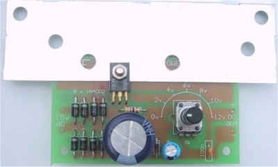
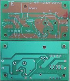
The
completed
POWER SUPPLY, showing
the placement of the parts
|
HOW THE CIRCUIT WORKS
First the mains voltage is reduced to a usable level
by the transformer. Two different low-cost transformers can be used. The M2155
is a 1 amp type and M2156 is a 2 amp type. This is the AC rating and when you
connect any transformer to a DC power supply circuit you must de-rate the
current rating by 30% to give the maximum DC current that can be delivered by
the power supply.
The reason for this the AC voltage is increased by 40%
when it is rectified and to maintain the VA (volt-amp) rating for the
transformer, the current rating must be decreased.
This means a 1 amp transformer will produce a 700mA
power supply and a 2 amp transformer will produce a 1.4 amp power supply.
For a low-cost power supply this output is quite
sufficient and is all we can get as quite a lot of heat will be developed in the
diodes, transistor and transformer when 700mA is flowing and literally burn
your finger when 1.4 amps flows.
The BD 679 regulator transistor must be heatsinked if
any more than 100-200mA is required and will certainly need a large heatsink
when the full rated current flows.
The heat generated in the transistor is due to two
factors. One is the current flow. Obviously, as more current flows, the
transistor will get hotter. But the other factor is the voltage across the
transistor. If you are drawing 100mA at 12v, the transistor will rise to a
certain temperature. If you reduce the output to say 6v, while still drawing
100mA, the transistor will get hotter because the voltage across it will be
greater. In the first case the voltage across the transistor will be the
voltage from the bridge rectifier minus the output voltage. Our figures were
22v - 12v = 10v across the transistor.
In the second case the voltages are:
22v - 6v = 16v.
In the first case the transistor will dissipate 1 watt
and in the second case 1.6 watts will be dissipated.
This is a 60% increase and is one of the hidden factors
behind heat-generation in a power supply.
Both transformers have a 15v AC output and the diode
bridge rectifies this voltage. The output of the bridge is termed unsmoothed
DC and if used to power an amplifier, for example, it will produce a very loud
buzz or hum from the speaker.
FEATURES:
0v to 12 volt output:
-
700mA with M 2155
- 1.4amp with M 2156
-
1A with 16v AC 1.5 amp plug pack
- 2 amp for short duration from 15v AC
train transformer
|
This unsmoothed DC is then fed to an electrolytic. The
function of the electrolytic is to charge on the voltage peaks
of the unsmoothed DC, then discharge into the load during the time between
the peaks. This smoothes the DC. The voltage will still fluctuate a
small amount during the charge/discharge cycle and if you connect it to an
amplifier, a small amount of annoying background hum will be produced. This
"hum" will be greatest when maximum current is required as the electrolytic is not
capable of delivering enough energy during peak requirements and the waveforms
becomes rippled.
The only way to improve this is to put high value
electrolytics on the board or use a simple electronic regulator in the form of
a transistor.
The Darlington transistor in the output is capable of
delivering the varying current while maintaining a constant voltage. It
does this by having an additional voltage available to it from the bridge
rectifier. The voltage on the output is adjustable from 0v to 12v via
a 5k pot. The pot gets is voltage from a zener regulated source and you can
pick off any voltage from 0v to 12v via the wiper. This stable voltage is fed
to the base of the Darlington transistor. The transistor is wired as an
emitter-follower. You can think of the transistor as a low resistance that
automatically varies according to the current requirement of the output. If
the load requires additional current, the normal effect would be for the output
voltage to drop according to ohms law, across the low resistance transistor.
But what happens in this case is the drop in output voltage turns ON the
transistor
so that it delivers the extra current from the power rail. In doing so, the
voltage may fall by as much as 2 - 3 v on the power rail but the output does not
see this as the regulator transistor is separating the voltage on the power
rail from the output.
DC
PLUG PACK
If you buy a DC plug-pack (wall wort) that is identified as 15v
DC @ 2 Amp, you will lose about 1.5v across the bridge and about 2v across
the transistor, so the max voltage will be 11.5v
If the plug pack produces 17v when not loaded and 15v when loaded, you may
get nearly 2 Amps output.
There are many factors that determine the maximum output current.
|
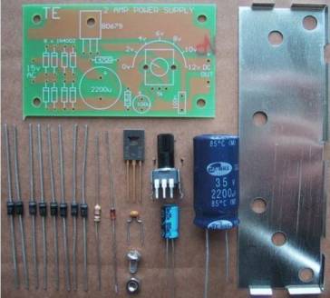
The
components for the 2-Amp Power Supply kit |
|
TWO AMP POWER SUPPLY
Parts List
Cost: $12.15 plus $6.50 postage
$12.50 with ammeter
Click
HERE to buy kit |
|
1 - 470R
1 - 10k mini pot with shaft (5k marked on PCB)
1 - 100n monoblock
1 - 2200u 25v PC mount electrolytic
1 - 100u 25v PC mount electrolytic
8 - 1N 4002 diodes
1 - 15v zener diode 400mW
1 - BD 679 Darlington transistor
1 - heatsink to suit BD 679 transistor (see text)
1 - nut and bolt for heatsink
1 - "movement" (shown as Side Panel Meter)
4 - 1R (resistors for converting to ammeter)
1 - 2R2
1 - 4R7
1 - 2amp power Supply PC board
EXTRAS:
1 - heatsink compound (small amount)
(use very thin layer of toothpaste)
7 - nuts and bolts for PC board, transformer and cord clamp
1 – M 2155 or M 2l56 transformer or 1.5amp 16v AC plug pack
1 - terminal block
1 - case to suit project - or plastic box
1 - power switch - SPDT
1 - terminal block or screw terminals for output
1 - power cord with plug
1 - plastic cord clamp
4 - 10cm hook-up flex (medium duty)
2 metres heavy-duty red output wire
2 metres heavy-duty black output wire
|
|
| Talking Electronics has many kits
for Model Railways and this kit makes use of the 15v AC output of
your train transformer to produce a very handy variable DC supply. |
|
|
Wiring
the power lead to the transformer and connecting the PC board |
CONSTRUCTION
All the components fit on to a small PC board with the
transistor at the edge of the board so that it can be screwed to a heatsink.
Fit the 8 power diodes first. These all align in the
one direction and the line on the board corresponds to the white or silver band
on the body of the diode.
Next fit the resistor, zener diode and 100n monoblock
capacitor. The zener looks like a signal diode and may have a number of
different markings on it. Sometimes it is marked with the zener voltage and
sometimes it has a code number. It may have 1N 5535 or 1N 5245 or IN 5861 or
even another number. Zener diode numbering is very messy, but they all refer
to a 15v zener. The mini pot is next to be fitted. If you want to mount the pot
on the front panel, it will be best to use a standard 5k pot with
shaft so you can fit a knob.
The two electrolytics are next, making sure the
positive lead goes down the hole marked on the overlay.
Finally, the BD 679 is fitted so that the heatsink goes
between the transistor and PC board (to provide the best heat transfer). See
below for more details on choosing the correct heatsink and applying thermal
grease to improve heat transfer.
An adequate heatsink is most important when
building a power supply, both to make it reliable and keep the components
operating within their temperature range.
When any of the parts get too hot you can introduce
unwanted hum (another name for ripple) or even create premature failure of
the diodes or transistor.
When all the components are fitted, and the heatsink is
in place, it can be placed in a suitable case, along with the power
transformer.
|
The
Artwork for the 2-amp power supply
The new boards in the kit have added heatsinking for the diodes. |
MAINS OPERATION
This project has two options. It can be a mains
operated project, using a 2155 or 2156 transformer or it can be connected to
a plug pack.
We recommend it be connected to a 16v
AC 1 amp plug pack as these are double insulated and provide
complete safety.
As we have mentioned in the introduction,
the 2 amp transformer M 2156 will not provide much more than 1.4 amps DC output
so the 1.5 amp AC plug pack has nearly the same rating.
By the time you buy a M 2156 transformer and power
cord, the total will be the same as the cost of the plug pack so it should be
one of your considerations.
|
Connecting
a plug pack to the 2-Amp Power Supply |
HEATSINK
The heatsink is one of the most important components
in a power supply. It must provide adequate heat dissipation to protect a
heat-sensitive device, from being damaged.
All power supplies dissipate heat. Some are more
efficient than others but whenever voltage and current are present together,
heat will need to be dissipated.
The heatsink in our project fits between the metal side
of the transistor and PC board to get direct contact with the transistor.
It is most important to get good thermal contact
so that any heat generated in the transistor will be carried away by the heatsink.
Since the transistor has a very small area for this
heat transfer, (all the heat must pass through the side of the transistor) it
is most important that the gap between the face of the transistor and the
heatsink be filled with thermal grease (thermal compound). Use a very thin
layer of ordinary toothpaste. You only need
a small amount smeared over the metal side of the transistor. The bolt is then passed
though the transistor, heatsink and PC board and the nut tightened until a
small amount is squeeze out from under the transistor. This proves
the nut is tight but it must not be too tight as you may damage the transistor
itself by cracking the case.
SIZE OF HEATSINK
The way to select the correct-size heatsink is to build
the project and fit a heat sink about 4cm x 10cm as a trial experiment. Next
you need some high wattage resistors or car lamps to load the power supply to
its maximum rating (this will depend on the transformer you use). Place one
finger on the transistor and another on the heatsink, about 2cm from the
transistor, and monitor the temperature rise in both positions. You should be
able to hold your finger for the duration of the experiment. If not, a
thicker heatsink is needed, as the one you are using is not transferring the
heat away from the transistor fast enough. The heatsink supplied in the kit is
thick and will dissipate about 8 watts.
AMMETER
The kit comes with a "Movement."
A movement is a moving coil with a pointer
with no resistors connected to the terminals.
The movement we supply is actually a SIDE PANEL METER that you convert to an
AMMETER.
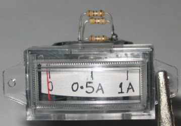
Any Movement can be converted to an ammeter, quite
easily.
To produce 0 -1 amp reading,
two 1R and one 4R7 (all in parallel) are
connected across the two terminals. These are called SHUNT RESISTORS.
The three shunt resistors can be clearly seen in the photo above.
To produce 0 - 2 amp reading, four 1R and one 2R2 are connected in parallel
across the terminals.
The kit contains a total of 6 resistors for this conversion.
All you have to do is open the movement and change the scale. You can put a
sticker over the scale and write 1A or 2A on the sticker.
HOUSING
The project should be housed in a small case,
preferably plastic, with either a flying lead on the output or a set of
terminals on the front of the case, marked with positive and negative.
The power cord must be anchored inside the case.
You can place a metal plate in the inside
of the bottom of the case to act as a chassis and this can be bent to form part
of the heatsink for the transistor.
If you are going to use a plug pack, the case
will be a lot smaller and a lot cheaper. You could even leave the project out
of a case and use the mini pot on the board as the voltage adjustment. I prefer
to leave things in their skeleton form, so I can see the "works" -
that's why I hardly ever suggest fitting a project into a case.
Decide carefully which arrangement you are going to
choose. Either way it will be a handy addition for your model railway or
workbench.
oooooooooooo000000000000000000000000oooooooooooooo
Here is the POWER SUPPLY module from Graham Stewart, in a case
with a digital voltage module showing the output voltage and banana plugs for
connecting leads.
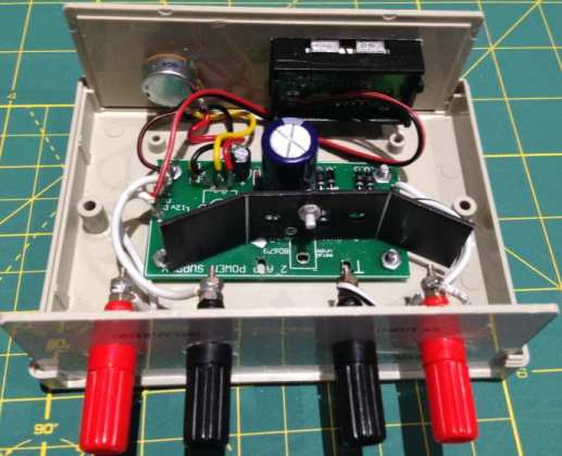
It's a nice power supply that you can build yourself and have the
satisfaction of learning about heatsinking.
|