|
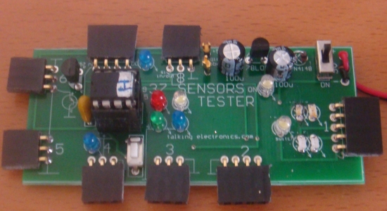
37 SENSOR
TESTING MODULE email Colin Mitchell for any queries. |
This project
tests
the 37 Sensors available on the web. These sensors come as a very
low-cost package - about $15.00 to $20.00 for all 37 modules for the
Arduino project !
And many buyers will use them
with this.
But there are many other applications and it is handy to
know what they do, how they work and how they perform. . . and knowing how to interface them to
your own projects.
The legend on the PC board shows the wiring to each of the
indicators and how they are connected to the module.
This
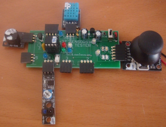
37 SENSOR TESTING MODULE
has 8 different "testing ports" and all you have to
do is plug a module into the correct connector and the results will be shown on LEDs or
from the
speaker (actually an active device containing an oscillator circuit,
producing a tone - also called a BEEPER or BUZZER) .
You will be able to test some of the modules yourself
with a few wires and a battery (and not need this TESTING MODULE), but other
modules need some or a lot of setting-up to get
a result.
Some modules have two different types, such as
for magnetic detection, IR detection and sound and with our project you will be able to
determine which is best for your application.
You will be able to see how the rotary encoder produces an output
(and
the output of the Joy Stick) as well as the humidity
and temperature sensor.
All the modules show different effects and have different sensitivities and
by seeing them in action, you
will be able to decide how to use them in your own projects.
Only one module is not tested.
The temperature-sensing transistor needs a microcontroller to
receive the data and display it. We have not done the coding for this
module, as
yet.
All the other modules are tested individually and for some, two modules are needed
to show the output
as one will be an indicating devices (such as the speaker - beeper-
active speaker - active tone producer).
But before you can start to test any of the modules, you must sort them out and number each module as shown in the
instructions below BEFORE doing any testing.
This is because each testing port has been designed to accept the
pins for a particular module and it matches the power rails as well as the
output pin on the sensor.
Some modules have reverse supply-and-ground pins, and you may damage
them if inserted into the wrong connector or around the wrong way.
Some modules have to be turned "up-side-down" and you put the "ID
number" on the underside to remind you of this.
Every module gets a number from 1 to 8 and some have 2 numbers. They also
get a number from 01 to 37 so you can easily find them in the list
below. Use
"white-out" and a "Jell-pen" to put the numbers on each module. Make a
nice, neat square of "white-out" and wait for it to dry before
writing
the numbers.
When you fit them to this project, you will have 35 experiments and then
you can combine two or more modules to increase the experiments to
more than 50.
This is a very interesting and challenging project.
And it will help you create your own projects.
You can also test other modules from the internet that have the same
pinout as our 37.
Most of them are duplicates of the 37 and are generally
more expensive.
This testing module was built to test each module and get some idea of
the performance you can expect when you put them into your own projects.
This discussion also explains how to interface each module to other
circuits or building blocks and provides the output capabilities of each
so you know how to connect them.
Basically, what we are saying is the modules lack UNIFORMITY. The pinouts
are all different and the activity of the output pin is not uniform.
The output of some modules goes HIGH when a signal is detected and some
go LOW.
The output of some will drive a LED very brightly while others will only
produce a weak glow.
However for 30 cents a module, who's complaining?
The kit of 37 modules offers a wide range of sensors and two of them
contain a microprocessor.
The author has not damaged a module, mainly because the 9v battery
cannot deliver a high current and the 78L05 shuts down at a current in
excess of about 100mA.
The uses for these modules is endless and and once you know their
effectiveness, you can start designing your own projects.
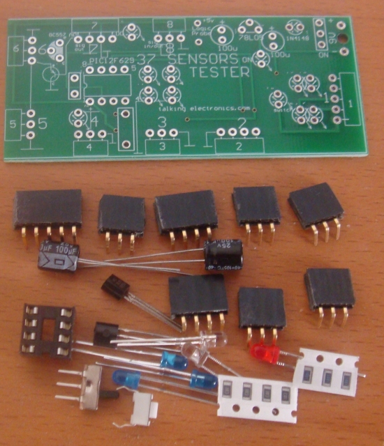
Kit of parts shown above has these additional parts included: PIC
Microcontroller, extension lead with sockets, 4 pin to 3 pin adapter,
LEDs for Joy Stick, pins for Logic Probe, 3-wire extension lead
with Male and Female ends, super magnet and 9v battery snap.
PARTS
LIST
Not in kit:
37 Sensor Testing Module
$12.00
plus
$6.50 post
Order a kit
2 - 220R resistors
1 - 2k2 resistor
1 - 10k resistor (surface mount)
1 - 100n monoblock
2 - 100u electrolytics
1 - 3mm red LEDs
1 - 3mm green LED
1 - 1N4148 diode
1 - BC 547 transistor
1 - 78L05 regulator
3 - blue 3mm LEDs
3 - white 3mm LEDs
3 - red 3mm LED
1 - green 3mm LED
2 - yellow 3mm LEDs
1 - PIC12F629 (with 37)
1 - 8 pin IC socket
1 - mini slide switch
1 - mini tactile switch
1 - 20cm extension lead 3-core
1 - 3-pin female socket
1 - 3-pin male plug
2 - machine pins for Logic Probe
5 - 3-pin female 90°
2 - 4 pin female 90°
1 - 5 pin female 90°
1 - small super magnet
1 - 9v battery snap
20cm very fine solder
1 - 37 Sensor PCB
1 - 9v battery
No sensor modules are included with the Sensor Testing
Module.
You can get
(That's what I did,
and it proved very interesting)
Most of the modules have a Chinese origin and
they are numbered from 001 to
040 from the designer, in the following list.
As you select each module, label it with the Port used to test it
and its Chinese reference number 01 etc. This will make testing a whole lot
easier, and prevent mistakes.
Here is a layout of the some of the modules and some others from a
supplier:
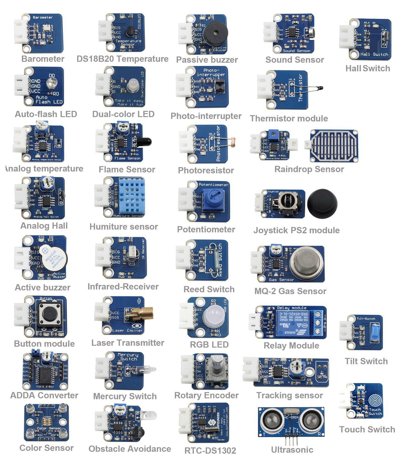
Click for larger image
Here are the names of the Modules in
Alphabetical order:
Here is the list of modules in "KY" order and the large numbers (alongside each image) represent the "Testing Port" number:
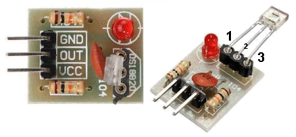
| KY-001 | Temperature Sensor Module: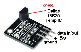 This
module is not yet tested in the 37 SENSOR test module. This
module is not yet tested in the 37 SENSOR test module. |
|||||||||||||||
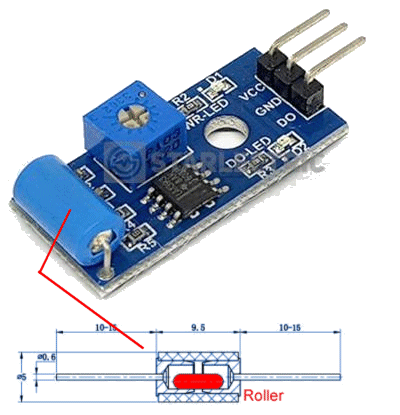
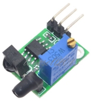
| KY-002 | Vibration Sensor: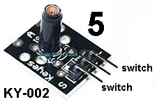 The
tube has a very weak spring and a stiff wire down the centre. When the
sensor is tapped the spring moves and makes contact with the central
wire. We call this module a "switch."
Only
the top and bottom pins connect to the switch. The "contact" will be
very VERY brief and you need a circuit that is capable of detecting a
short "pulse." The
tube has a very weak spring and a stiff wire down the centre. When the
sensor is tapped the spring moves and makes contact with the central
wire. We call this module a "switch."
Only
the top and bottom pins connect to the switch. The "contact" will be
very VERY brief and you need a circuit that is capable of detecting a
short "pulse."Connect to port 5 and place active speaker in Port 6. Flick the sensor and the speaker (buzzer) will give a short chirp. |
KY-003 | Hall Effect Sensor: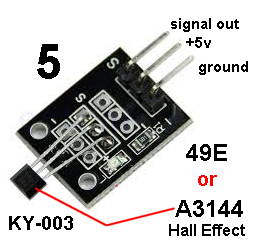 The 37 Sensor test module comes with a super
magnet to test the magnetic sensor modules.
The 37 Sensor test module comes with a super
magnet to test the magnetic sensor modules. Fit the Hall Effect Sensor to Port 4. Bring a magnet up to the face of the Hall device and the LED will turn ON. The Hall device has a switch (transistor) that connects the signal pin to the ground pin. The "signal out" goes from HIGH to LOW - instantly. The circuit contains a Schmitt-trigger to do this. If you want to detect gradual increase in magnetic strength, use KY-024. See module KY-035 and compare the two. |
|||||||||||||
| KY-004 | Key Module (switch Module):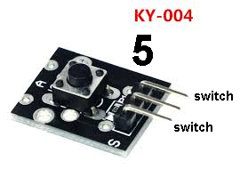 Fit
the Key Module to Port 5 and place the active speaker in Port 6. Fit
the Key Module to Port 5 and place the active speaker in Port 6.Push the button and the speaker (buzzer) will produce a tone. This is called a "key" or "push-button" or "switch." |
|||||||||||||||
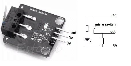
| Not in the kit | MICRO SWITCH: This CRASH SENSOR module is simply a micro switch. The output goes HIGH when the leaver of the micro switch is pressed. This is called an ACTIVE HIGH output.
|
|||||||||||||||
| KY-005 | Infra Red Transmitter LED: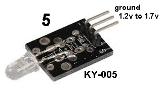 This
is an Infrared LED so you cannot see the light it produces. This
is an Infrared LED so you cannot see the light it produces. You have to set up a number of features of the 37 Sensor Testing Module to detect the LED. You need to fit Module KY-014 (the Heartbeat Detector) to Port 4. Now fit the extension lead to Port 3 with the white-out showing on the lead. Fit module KY-005 to this lead. Now fit the mini Active buzzer to port 6 and this will provide the current limiting for the IR LED on Port 5. The buzzer will produce a continual tone. Now bring the IR LED module KY-005 up to the LEDs on module KY-014 and the LED on the 37 Sensor board will come ON to show the IR receiving LED is working and the IR transmitting LED is working. |
|||||||||||||||
| KY-006 | Mini Speaker (diaphragm):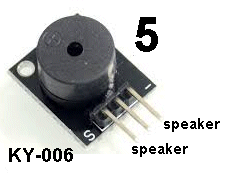 This
is just a mini speaker and requires a circuit to drive it. It is just an
electromagnet and a diaphragm. This
is just a mini speaker and requires a circuit to drive it. It is just an
electromagnet and a diaphragm. But we can create a very clever trick. Fit the active speaker KY-009 to Port 6 and this Mini Speaker KY-006 to Port 5 and both will produce a tone. Cover the hole on each to hear this. The active speaker is drawing more current and less current during each cycle and the Mini Speaker detects this. |
|||||||||||||||
| KY-007 | Rotary Encoder Module: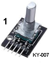 Fit
the Rotary Encoder Module to Port 1 and turn the shaft VERY SLOWLY. Fit
the Rotary Encoder Module to Port 1 and turn the shaft VERY SLOWLY. The white signal LED will come on and then the red LED will change to green. When the shaft is turned in the other direction, the red LED will change to green and then the white signal LED will come on. This is how you can work out which way the shaft is being rotated. |
|||||||||||||||
| KY-008 | Red Laser Module:
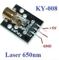 Commonly
called: 5mW Laser Diode - transmitter. Commonly
called: 5mW Laser Diode - transmitter.Fit the Laser Module to Port 6 and the Key Module KY-004 to port 5. Push the switch and the Laser will produce a red dot up to 10 metres onto a wall. Do not look directly into the laser as it will damage your retina. The module takes about 28mA. The Laser diode only requires about 1.2v to 1.7v and a 92 ohm resistor has been soldered onto the side of the printed circuit board of the laser module so the module can be connected to a 5v supply. The 10k resistor on the board does nothing. You can use the LDR (Photo resistor) KY-018 (fitted to port 5) to detect the Laser or the Laser Receiver described in the following box or KY-014 (the Heartbeat Detector) fitted to Port 4. The Laser transmitter module, transmits a wavelength of 650nm (red) and gives a narrow intense beam. Take care of your eyes. Do not look directly into the beam. Power consumption: about 30mA at 5v. |
|||||||||||||||
| Not in the Kit |
Laser Receiver:
 The 3-leaded component (fitted to the board in a 3-pin socket) is a light-detecting diode with an amplifier. The output 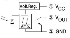 can
only go LOW (see the circuit diagram and note the transistor can only
"sink." The transistor will pass about 20mA. can
only go LOW (see the circuit diagram and note the transistor can only
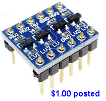
"sink." The transistor will pass about 20mA. The module can be purchased on eBay for $1.00 posted. It is called: Laser Receiver Module non-modulator Tube Laser Sensor Module. The term "non-modulator" is Chinese for the fact that is receives any source of Infra-red (IR) radiation and it is not like the IR receiver KY-022 that only detects radiation that is pulsing at a frequency of 38kHz. It receives ALL TYPES of laser signals. Technically it is: Non-Modulated. Or Not Modulated You will need to surround the active part of the receiver with a black tube to prevent light from the room interfering with the reception. NOTE: The "chip" (Laser Receiving Module) MUST be fitted as shown in the photo above. Do NOT follow the legend on the PC board as it refers to a temperature module. |
|||||||||||||||
| KY-009 | 3 Colour LED: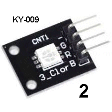 Fit
the 3-colour LED Module to Port 2 and the micro will send varying width
pulses to each colour to produce 30 different effects and allow the module
to display its 16,000 colours during some of these effects. Fit
the 3-colour LED Module to Port 2 and the micro will send varying width
pulses to each colour to produce 30 different effects and allow the module
to display its 16,000 colours during some of these effects. Push the button next to the micro to advance to the next sequence. At the end of each sequence is a "dead zone" and if the button is pressed before and during this time, the micro advances to the next sequence. The module does not have any current-limiting resistors and cannot be connected directly to any supply. |
|||||||||||||||
| KY-010 | Optical Interrupter
Module: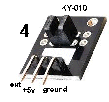 Fit
this module to Port 4 and insert a piece of paper into the slit. Fit
this module to Port 4 and insert a piece of paper into the slit. The LED on the Testing Module will extinguish. This module can be used with a toothed wheel to detect rotation or detect the end-of-travel of a moving object. The "out" pin gets connected to the ground pin via a transistor (the receiving detector) when nothing is in the slit. In other words, it is ACTIVE LOW. |
|||||||||||||||
| KY-011 | 2 Colour LED 5mm: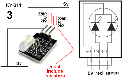 This module is fitted to Port 3 and the micro sends 30 different sequences and the 2-colour LED shows the results. (the TEST MODULE has current-limiting resistors) No current-limiting resistors on the KY-011 or KY-029 module. It cannot be connected directly to any supply. See also KY-029 for 3mm version |
|||||||||||||||
| KY-012 | Active Buzzer: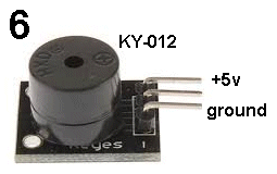 Fit this module to Port 6 and the switch module to Port 5. Push the button and the Buzzer will produce a tone. The buzzer has a transistor and components inside the case to produce the tone. If the Mini Speaker (diaphragm) KY-006 is fitted to Port 5, both will produce a tone. |
|||||||||||||||
| KY-013 | Temperature Sensor: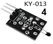 Fit
this module to Port 4 and the LED on the Testing board will illuminate.
Touch the thermistor and the LED will increase in brightness. Fit
this module to Port 4 and the LED on the Testing board will illuminate.
Touch the thermistor and the LED will increase in brightness. Wet the thermistor and blow on it and the LED will extinguish. |
|||||||||||||||
| KY-014 | Detect Heartbeat: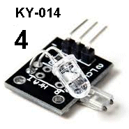 This
module is fitted to Port 4 UP-SIDE-DOWN. This
module is fitted to Port 4 UP-SIDE-DOWN. Paint the number 4 on the UNDERSIDE of the module so you do not insert it around the wrong way. Put your finger between the transmitting LED (clear LED) and the receiving LED (square LED) and the LED on the Testing Board will vary in brightness. No current-limiting resistors on the module. It cannot be connected directly to any supply. |
|||||||||||||||
| KY-015 | Temperature and Humidity Sensor: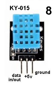 Make sure the power to the 37 Sensors Testing Module is OFF. Fit this module to Port 8 and press the switch near the micro and keep it pressed. Now switch ON the supply and the micro will advance to the Humidity section of the program for the Temperature and Humidity Sensor. It will wait for about 3 seconds to allow the sensor to settle and then send a request to the module. The module will reply via the 4 LEDs next to the micro. The two top LEDs will blink to show the percentage humidity and the lower two LEDs will show the temperature in degrees C. The cycle will then automatically repeat.
|
|||||||||||||||
| KY-016 | 3-Colour LED: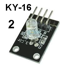 This
module is fitted to Port 2 and the micro sends 30 different sequences
and the 3-colour LED shows the results. This
module is fitted to Port 2 and the micro sends 30 different sequences
and the 3-colour LED shows the results. The red, blue and green chips inside the LED will produce white light during parts of each sequence. 3 x 150R current limiting resistors on the module allow it to be connected to a 5v supply - if you want to test it yourself on a 5v to 6v supply. |
|||||||||||||||
| KY-017 | Mercury Tilt Switch: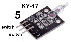 Fit the Mercury Switch (Tilt Switch) to Port 5 and the active buzzer to Port 6. Tilt the mercury Switch and the buzzer will produce a tone. |
|||||||||||||||
| KY-018 | Photo Resistor - Light Dependent Resistor - LDR: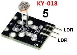 Fit the module to Port 5 and the active buzzer to Port 6. Bring the LDR towards a very bright light and the buzzer will produce a tone. This shows the resistance of the LDR is decreasing to a value about 100 to 300 ohms. The dark resistance will be as high as 100k. |
|||||||||||||||
| KY-019 | Relay Module: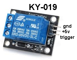 Fit the Relay Module to Port 8. Push the button next to the micro. This will remove the trigger voltage and the relay will turn off. When the trigger voltage is HIGH, the transistor on the Relay Module will activate the relay. It requires less than 1mA to activate the relay as the transistor has a gain of about 100 and the trigger voltage can be as low as 3v. The output terminals on the relay will switch a load up to 10 amps, but should be less than 3 amps for safety. |
|||||||||||||||
| KY-020 | Tilt Switch: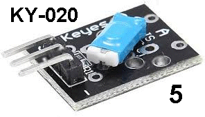 Fit
the Tilt Switch to Port 5 and the active buzzer to Port 6. Fit
the Tilt Switch to Port 5 and the active buzzer to Port 6. Tilt the Switch and the buzzer will produce a tone. The switch contains a ball and it rolls against two contacts. It does not make very good contact and is not reliable. |
|||||||||||||||
| KY-021 | Magnetic Reed Switch: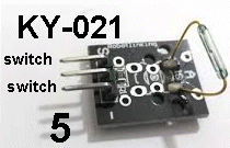 Fit
the reed switch to Port 5 and the active buzzer to Port 6. Fit
the reed switch to Port 5 and the active buzzer to Port 6. Bring a strong magnet towards the reed switch and the buzzer will produce a tone. |
|||||||||||||||
| KY-022 | Infra RED Receiver: 38kHz detection 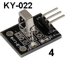 Connect
the IR Receiver module KY-022 to the extension lead provided with the 37
Sensor Testing module and fit the lead into Port 4. Connect
the IR Receiver module KY-022 to the extension lead provided with the 37
Sensor Testing module and fit the lead into Port 4.Fit the Obstacle Avoidance Module KY-032 into Port 7. Bring the IR Receiver module near the transmitter LED and the LED at Port 4 will illuminate. Even though the IR Receiver Module sees a constant IR beam, the electronics inside the IR Receiver module only produces a short output pulse. You have to increase, decrease or remove the IR signal for the receiver to output another pulse. This is very important to remember. You will think the signal is stopping, but the output is only active for a short time during each detection. The IR Receiver Module is: VS 1838B. The IR receiving module on KY-032 is HS38BD and it produces a constant output when 38kHz is detected. |
|||||||||||||||
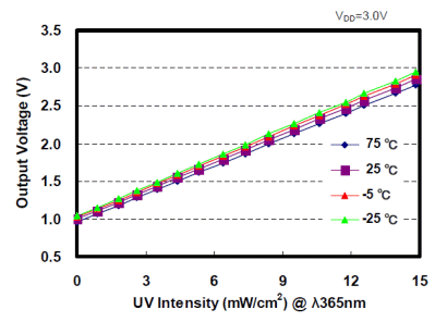
| Not in the kit | ULTRA VIOLET LIGHT DETECTOR This module shown in the image below is the cheapest on the web, at $3.00 posted. Other, similar modules are more expensive ($5.00) It contains a micro-controller and produces a reading of between 1 and 15, when it detects ultraviolet light. The scale below shows the danger of being exposed to a high reading.
|
|||||||||||||||
| KY-023 | Joystick Module: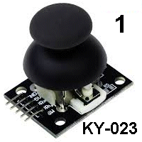 Fit
the Joystick Module to Port 1. Fit
the Joystick Module to Port 1. Move the Joystick and watch the LEDs gradually dim and gradually increase in brightness. The joystick contains two 10k pots and a switch. Press the joystick and the white indicator LED illuminates. More discussion HERE. |
|||||||||||||||
| KY-024 | Linear Magnetic Hall Sensor: Fit
the module into Port 7 and the active buzzer into Port 6. Fit
the module into Port 7 and the active buzzer into Port 6. Turn the multi-turn pot until the buzzer stops buzzing. Now bring a magnet towards the Hall Sensor and the buzzer will increase and decrease in volume. |
|||||||||||||||
| KY-025 | Magnetic Reed Switch: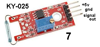 Fit
the module into Port 7 and the active buzzer into Port 6. Fit
the module into Port 7 and the active buzzer into Port 6. Bring a magnet towards the Reed Switch and the buzzer will turn on. The Pot does nothing. The output goes LOW when the Reed Switch is closed and it will only deliver a few milliamp in the LOW condition. The 37 Sensor Testing board has a buffer transistor (interface transistor) to allow 28mA for the buzzer. This module is no better than just a Reed Switch. |
|||||||||||||||
| KY-026 | Flame Sensor - IR Sensor: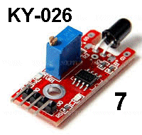 Fit
the module to Port 7 and bring the module towards an incandescent light,
LED light and Compact Fluorescent light and see how much IR radiation
they produce. Fit
the module to Port 7 and bring the module towards an incandescent light,
LED light and Compact Fluorescent light and see how much IR radiation
they produce. You can also connect the extension lead to Port 4 and fit the Infra Red Transmitter Module KY-005. Now bring the Infra Red Transmitter Module towards the IR Sensor Module and note the sensitive parts of the receiving LED. |
|||||||||||||||
| KY-027 | Magic Light Cup - Tilt Switch: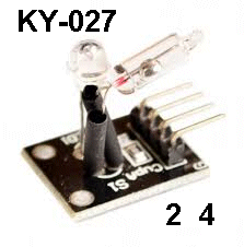 The kit comes with two of these modules. Fit them to Ports 2 and 4 UP-SIDE-DOWN, to see the mercury switch activate and the LED illuminate. The mercury switch doe snot activate the LED on the board. This is two different experiments. |
|||||||||||||||
| KY-028 | Temperature Sensor: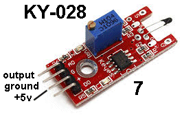 Fit
the KY-028 module to Port 7. Fit
the KY-028 module to Port 7.Fit the Active Buzzer KY-012 to Port 6. Bring the Temperature Sensor (the thermistor at the end of the module) towards a hot lamp. The tone of the buzzer will increase. |
|||||||||||||||
| KY-029 | 2-Colour LED 3mm: This
module is fitted to Port 3 and the micro sends 30 different sequences
and the 2-colour LED shows the results. See also KY-011 for 5mm
version This
module is fitted to Port 3 and the micro sends 30 different sequences
and the 2-colour LED shows the results. See also KY-011 for 5mm
version This module has no current-limiting resistors (the resistor on the board is ZERO OHMS) and needs resistors as shown for KY-011. |
|||||||||||||||
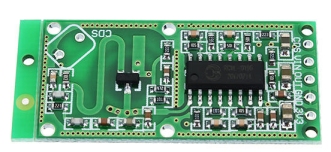
| KY-030 | Microphone Module: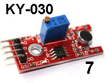 The
kit of 37 sensors includes two identical microphone modules. Fit the
Module to Port 7 and the active Buzzer module
KY-012 to Port 6. The
kit of 37 sensors includes two identical microphone modules. Fit the
Module to Port 7 and the active Buzzer module
KY-012 to Port 6.Turn the 10-turn pot until the sound from the buzzer stops. Now blow into the microphone and the buzzer will produce a sound. The fourth pin on the module is a DIGITAL OUTPUT. The chip can only drive LOW and a LED is on this line and it glows when the line is LOW. Turn the 10-turn pot slowly and a point will come when the LED turns ON. Turn the LED OFF and whistle into the microphone and the LED will flicker. This is the point of greatest sensitivity. See also KY-037 See the discussion on this module - not a good module. |
|||||||||||||||
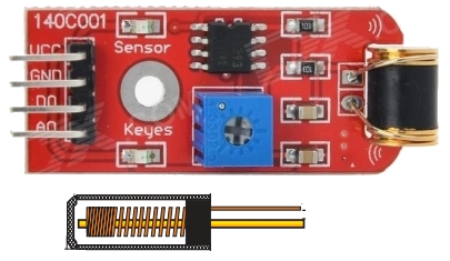
| KY-031 | Knock Sensor: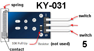 Fit
the module to Port 5 and the active Buzzer module
KY-012 to Port 6. Fit
the module to Port 5 and the active Buzzer module
KY-012 to Port 6.Knock the sensor and the buzzer will beep.
VIBRATION SENSOR - do
not buy !! VIBRATION SENSOR -
a good design |
|||||||||||||||
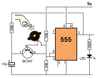
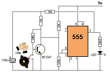
| Not in the kit | TAP SENSOR - vibration sensor - PIEZO
VIBRATION SENSOR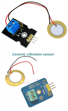 The
PC board has no amplifying components and the piezo diaphragm is simply
connected to the two outer pins. The
PC board has no amplifying components and the piezo diaphragm is simply
connected to the two outer pins.In theory you have to hold the outer rim of the piezo diaphragm and tap the centre so the disc is "pushed in." It will produce a voltage as high as 10v to 20v, depending how hard you tap it and the quality of the piezo diaphragm. The current produced by the disc is only a few microamps and it must be connected to a high impedance amplifier to detect the results. The "tap signal" is very brief and to detect it you need a high gain circuit. The following two 555 circuits can be built to show the effectiveness of the diaphragm. The first circuit is TAP-ON TAP-OFF and the second circuit is CLAP-ON CLAP-OFF. More details can be found HERE
|
|||||||||||||||
| KY-032 | Obstacle Avoidance Module: uses 38kHz
transmission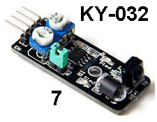  Bend
the 4th pin of the module sideways and fit the 3 pins into the 4-pin
socket as shown. Bend
the 4th pin of the module sideways and fit the 3 pins into the 4-pin
socket as shown. Adjust the two pots while bringing your hand towards the module and see when the module detects an obstacle. See the discussion on this module
|
|||||||||||||||
| KY-033 | Hunt Sensor Module: IR but no
38kHz coding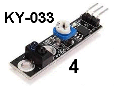 Fit
the module to Port 4 and adjust the pot until the LED goes OFF. Fit
the module to Port 4 and adjust the pot until the LED goes OFF. Now bring your finger up to the sensors and the LED will illuminate. Touch one detector at a time and note there is no effect. The module is only picking up a signal from the transmitter to the receiver. This eliminates background illumination. See the discussion on this module |
|||||||||||||||
| KY-034 | Flashing Colour 5mm LED: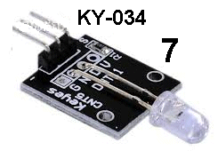 Fit the 3 pins into the 4-pin socket as shown.
 The LED will produce a wide range of effects and colours.
|
|||||||||||||||
| KY-035 | Magnetic Sensor: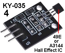 Fit
the Module to Port 4 and bring a magnet close. Note how the sensor is
sensitive to the N-pole. Fit
the Module to Port 4 and bring a magnet close. Note how the sensor is
sensitive to the N-pole. See module KY-003 and compare the two. |
|||||||||||||||
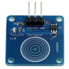
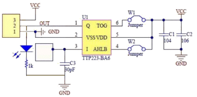
| KY-036 | Touch Sensor: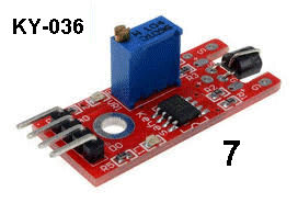 Fit
the module to Port 7 and the active Buzzer module KY-012 to Port 6. Fit
the module to Port 7 and the active Buzzer module KY-012 to Port 6.Touch the lead on the FET detector and the buzzer will produce a sound. Touch other parts of your body on sections of the 37 Sensor Testing board and not the effect.
This module is very sophisticated because
it is very difficult to get a reliable detection from a finger without
the finger touching a metal plate. |
|||||||||||||||
| KY-037 | Microphone Module: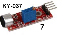 The
kit of 37 sensors includes two identical microphone modules. Fit the
KY-037
Module to Port 7 and the active Buzzer module
KY-012 to Port 6. The
kit of 37 sensors includes two identical microphone modules. Fit the
KY-037
Module to Port 7 and the active Buzzer module
KY-012 to Port 6.Turn the 10-turn pot until the sound from the buzzer stops. Now blow into the microphone and the buzzer will produce a sound. Alternatively, you can detect audio by fitting the 3-wire extension lead to the first 3 pins of the module and into the first 3 pins of Port 7. Turn the 10-turn pot anticlockwise until the "activity" LED on the module goes out. Now place the mini speaker module KY-006 into Port 6 and turn the 10-turn pot clockwise until the LEDs on the testing module start to dim. This shows the output of the Microphone Module is starting to drive the mini-speaker via the transistor on the testing module. Now talk into the microphone and you will hear the result from the mini speaker. The fourth pin on the module is a DIGITAL OUTPUT. The chip can only drive LOW and a LED is on this line and it glows when the line is LOW. Turn the 10-turn pot slowly and a point will come when the LED turns ON. Turn the LED OFF and whistle into the microphone and the LED will flicker. This is the point of greatest sensitivity. See also KY-030 See the discussion on this module - not a good module. You can also get this module from a different supplier. It has the same performance but you will have to make an adapter to fit it to Port 7 as the pinout does not match the Testing Module. This module is much more sensitive than KY-037 as it has a transistor amplifier stage to give a gain of 50 to produce a very sensitive microphone that will produce feedback when testing and a very clear pick-up from the surroundings. It can be found on eBay: 5 pcs Sound Detection Sensor Module Sensor for Arduino ($4.00 posted) 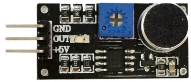 |
|||||||||||||||
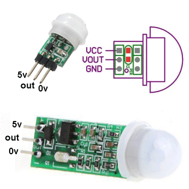
| Not in the kit | PIR DETECTOR: There are 3 low-cost PIR detectors on eBay for less than $2.00. They detect the temperature of the human body and the output goes HIGH. Some of these modules have a 1 minute delay when turned ON, to let the PIR detector to settle and allow you to move away from the detecting range. Here is a circuit that uses the PIR module. It has mini trim pots to adjust the sensitivity and timing. You can see the output pins are 0v, 5v and OUT. 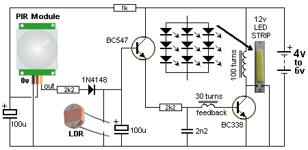
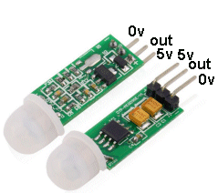 These PIR modules have different pin-outs and you need to check before
fitting them to the test equipment.
These PIR modules have different pin-outs and you need to check before
fitting them to the test equipment. 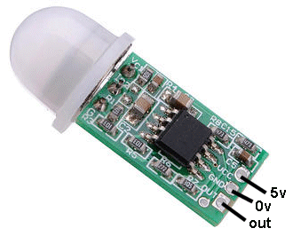 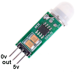 7133-1
is a 30mA voltage regulator with and output of 3v3. 7133-1
is a 30mA voltage regulator with and output of 3v3.7530M is a 100mA voltage regulator IC with an output of 3v.
|
|||||||||||||||
| Not in the kit | Rain Sensor: Also called water sensor or touch sensor. The tracks are like two interleaving combs and and moisture touching two tracks will create a resistance. The op-amp will create an amplification factor and suppose the resistance of your finger is 75,000 ohms. This will create a certain current-flow through the sensor and through the input of the amplifier. The amplifier will increase the amount of current and allow the increased current to flow through the output of the amplifier. Suppose it has an amplification-factor of 100. This means the the 75,000 ohms will be reduced by 100 to get 750 ohms. A 750 ohm resistor in series with a LED will make it illuminate. The amplification-factor could be as high as 200 to 500, so the LED will be very bright. The digital output on our prototype changed state as soon a 4 drops were detected and the analogue output changes slowly as each drop is detected. There a number of different modules on the web for $1.00 posted and you can use them as a touch sensor or as a water-level detector. 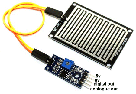 There are two identical modules available on the web but the pin-outs are REVERSED. Use only the digital output as it turns on the buzzer instantly. Either sensor can be fitted to any module. The module below has the 5v pin as the first pin. Bend the analogue pin out of the way so it will not fit down the socket. Now turn the module over and fit the 3 straight pins down the first 3 holes of the socket on Port 7. The legend on the PC board show the first pin of the socket is signal out, then 0v and then 5v. Fit the buzzer to Port 6 and turn the pot on the module until the sound stops. Now wet your finger and press hard on the RAIN GRID PC board and the buzzer will produce a tone. The circuit is not very sensitive. SOIL MOISTURE: 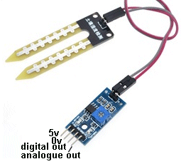 Fit
this module to Port 7 via the 3-wire test lead by using only the 5v, 0v
and digital-out pins. Fit
this module to Port 7 via the 3-wire test lead by using only the 5v, 0v
and digital-out pins. Turn the lead over and fit the other end into the first 3 pins of Port 7. Now fit the Active Buzzer KY-012 to Port 5. Adjust the pot until the red LED goes out. Now press firmly on the two probes with wet fingers and the mini speaker/buzzer will produce a tone. This module is also called a hygrometer. A hygrometer measures the amount of water or water vapor in air or soil. A hydrometer measures the density of a fluid such as sulphuric acid in a battery when it is fully charged. WATER SENSOR: |
|||||||||||||||
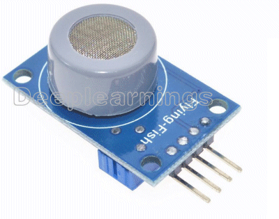
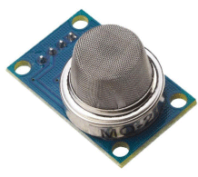
| Not in the kit | GAS SENSOR: There are a number of gas sensors on the web for less than $3.00 to detect all types of different gasses.
|
|||||||||||||||
| Not in the kit | TRAFFIC LIGHTS: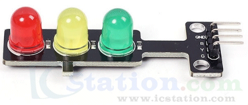 This module is designed for Arduino projects and is available from IC Station for $1.00 plus postage. This is the only supplier for this module. It has current limiting resistors (see the tiny surface mount resistors) and the module can be connected to 5v supply. |
|||||||||||||||
| Not in the kit | AIR PRESSURE SENSOR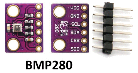 This module is for sale on eBay for $1.00 posted. |
|||||||||||||||
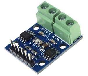
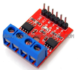
| Not in the kit | FAN MODULE: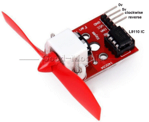 The
module contains a motor with propeller and a MOTOR-DRIVER IC. The
module contains a motor with propeller and a MOTOR-DRIVER IC. This chip (IC - Integrated Circuit) has an 800mA bridge that is capable of reversing the motor. Input-A turns the motor clockwise and this means you only need an input called a DIGITAL LINE to turn the motor ON. Input-B rotates the motor in the other direction. The digital line just needs to be 3v or higher and less than 1mA will activate the input. The chip does all the rest. This module is available on 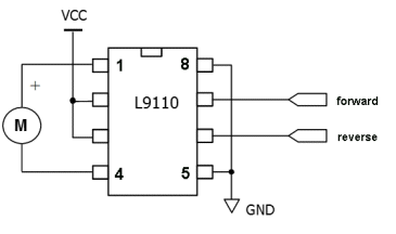 eBay for
$3.00 posted. eBay for
$3.00 posted. You can use the IC and motor (or another motor and gearbox) to drive a car in forward and reverse.
You can also get the L-9110 on a DUAL
module for $1.00 posted. |
|||||||||||||||
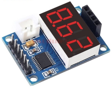
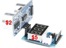
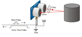
| Not in the kit | ULTRASONIC MODULE: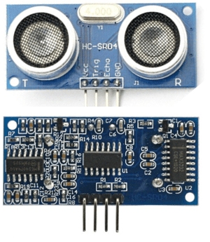 This ultrasonic module is available on eBay for $2.00 posted,
but it does not offer any more capability than KY-032 (obstacle
Avoidance Module) or KY-033 (Hunt Module - for very close detection) or
PIR Detector (for people detection) or KY-022 (for 38kHz IR detection)
or KY-018 (Photo Resistor - for light detection) or KY-010 (detects
item placed in slit on receiving detector) or KY-003 (detects magnets). This ultrasonic module is available on eBay for $2.00 posted,
but it does not offer any more capability than KY-032 (obstacle
Avoidance Module) or KY-033 (Hunt Module - for very close detection) or
PIR Detector (for people detection) or KY-022 (for 38kHz IR detection)
or KY-018 (Photo Resistor - for light detection) or KY-010 (detects
item placed in slit on receiving detector) or KY-003 (detects magnets).There are many alternatives and SR-04 module is big and ugly and is really only useful if you want to know the distance to an object.
Here's how to fit the SR-04 module: No
setting-up required.
Just plug the $2.00 HC-SR04
into the $5.00 Display Board and connect 5v to the two pins of the white
socket. The 3-digit display will illuminate and show the distance
to the closest object (in cm). If other walls are nearby, the reading
will be inaccurate.
|
|||||||||||||||
| Not in the kit | COLOUR RECOGNITION These two modules are the same. 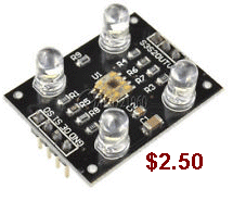 But
they have different pin-outs and the $3.50 module will accept different
lens screwed into the holder. (the lens are difficult to buy). But
they have different pin-outs and the $3.50 module will accept different
lens screwed into the holder. (the lens are difficult to buy). 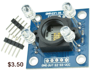 |
|||||||||||||||
| Not in the kit | DELAY MODULE: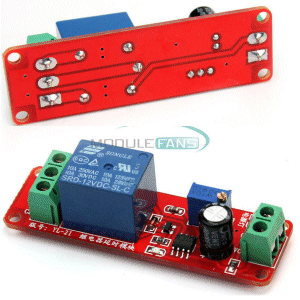 When power is supplied to this module via the 2-pin screw terminals, the relay will not operate for a delay of 1 second to 10 seconds. This module is made and sold by only one manufacturer and they have sold over 3,000 modules for less than $1.50 each incl postage. . |
|||||||||||||||
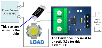
| Not in the kit | 3WATT LED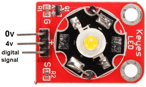 This module has not been described fully or correctly on the web. The LED is 3watt and it can be supplied with a current of 700mA. It is driven (turned ON and OFF) by transistor Q1. The current-limiting base resistor for the transistor is 1k and with a digital signal of 5v, the transistor will hopefully be saturated and allow a current up to 700mA to flow. BUT the supply must be 4v as the characteristic voltage across the LED will be a maximum of 3.6v and the drop across the transistor will be about 0.2v If the supply is higher than 4v, the current-flow though the LED will be greater than 700mA and it will be damaged. If you use a 5v supply, you must include a 1R5 (1 watt) resistor. This resistor will drop 0.7 x 1.5 = 1.05v No-one has mentioned these requirements on the web. 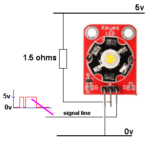
If you don't include the LOAD resistor, either the LED will burn out or the transistor will be damaged.
|
|||||||||||||||
| Not in the kit | ANEMOMETER (wind speed detector) 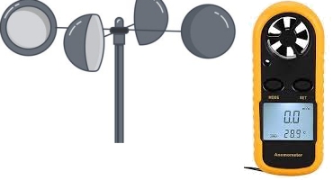 Normally, wind speed is measured with rotating cups or a fan (as shown above). But these are mechanical devices and eventually wear out. Wind speed can also be measured with a "hot wire" or ultrasonic piezo's that measure the time taken for sound to travel through a windy passage of air. Wind speed can also be measured with a set of 4 pressure sensors and it just takes a bit of calculating to work out the wind speed. You can also measure wind speed by passing current though a thermistor and the wind will cool it down and increase the current. You also need to know the temperature of the air and the "wind-chill-factor" to calculator the velocity. But it can be done.  You can buy all these components very cheap on eBay and the place to start is the Pressure Sensor shown on the left, using the MBP280 sensor module and costs just $1.00. Place 4 of them in 4 very small plastic bottles with a small hole in the side and these holes are on the 4 sides of a square. The wind will blow into one hole, pass two holes and not blow into the 4th hole. Each sensor will detect a different pressure and you will be able to work out the velocity when you test the instrument out the window of your car when travelling at 20km/hr to 100km/hr. The whole idea is to be able to do this for very little cost. You can buy these for $2,000, but why not do it yourself. |
|||||||||||||||
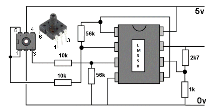
| Not in the kit | WATER DEPTH 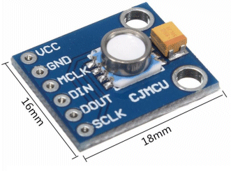 The module above detects 10mbar to 1100mbar pressure (110kPa - 16psi) and costs $12.00 The simplest water level indicator is shown in the following circuit:  Barometric Pressure
Sensor Module |
|||||||||||||||
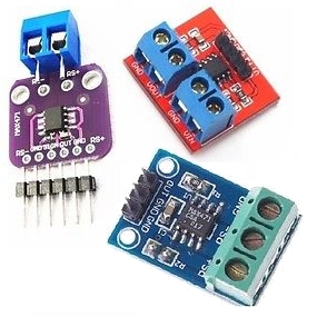
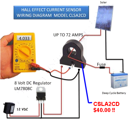
| Not in the kit | CURRENT SENSE MODULE: 0 - 3 amp All these modules are referred to as "cut the wire." You need to cut one of the wires carrying the current and insert the CURRENT SENSE RESISTOR. There are other modules called NON-INVASIVE. They use either a HALL EFFECT deice to detect the magnetic field produced by the current-flow or one wire is inserted into the centre of a coil consisting of thousands of turns. Your wire is classified as ONE TURN of a STEP-UP transformer and the output of the is connected to a LOAD. When the voltage across the load is measured, the value is converted into amps flowing through the "inserted wire."
 Unless you have a specific need for a CURRENT SENSE MODULE, you can use the 10 amp range on a digital multimeter to determine the LOAD current. Here is a 0 - 20Amp Current Sense module using a hall effect device, built into the chip. The module costs about $2.50 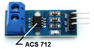 Don't forget. These modules are NOT ISOLATED. That means the wire you are testing has a path through the module and appears on the output. Suppose you are testing 240v AC. The module is SITTING AT 240V ac !! In other words, you cannot touch the output !!! These modules are only suitable for testing LOW VOLTAGE - so you can't get a shock. If you want to measure high voltage, you will need a CURRENT TRANSFORMER (for isolation). You need to place ONE WIRE through the center of the transformer and keep the other wire away, so it has absolutely no influence on the reading (although the influence will be microscopic when the wire is away from the centre of the coil). These modules will ONLY MEASURE AC - because the action is called TRANSFORMER ACTION. Don't get confused. The coil shown in the
following image is NOT a CURRENT SENSE Transformer. It is a HALL EFFECT
device called CLSA2CD
Honeywell Current Sensor Hall Effect Transducer.
Only a Hall Effect device will detect DC.
The CSLA2CD costs more than $40.00 and if you are going to measure low voltage, use one of the $1.50 or $2.50 modules above. |
|||||||||||||||
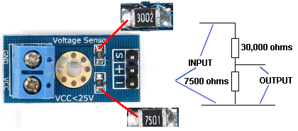
| Not in the kit | VOLTAGE SENSOR: This module is just a voltage divider so that voltages up to 25v can be read by the Arduino module.
|
|||||||||||||||
| Not in the kit | LEVEL SHIFTER - LEVEL CONVERTER See more details HERE
|
|||||||||||||||
| Not in the kit | 3 TRACK SENSOR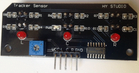  This module has 3 IR transmitting LEDs and 3 IR receiving LEDs in 3 identical packages -all on the PC module. It will detect a black line on a piece of paper etc but it is large and quite unsuitable for small projects. It is far too big!! The outputs are "L" for left, "C" for centre and "R" for right. The IR signal is not coded (such as 38kHz) and the illumination in the room will have an effect on its sensitivity. You can connect it to the two centre pins of Port 7 via an adapter or jumper leads and as you bring the module towards a surface, the LEDs on the module will illuminate. Available on eBay: 3CH CTRT5000 Track Sensor Infrared Line Shield Module For Arduino AVR Robot for $2.50 posted. I think two KY-033 would be much better and neater. You only need two, straddling the black line. |
|||||||||||||||
| Not in the kit | PRESSURE SENSOR (weight sensor)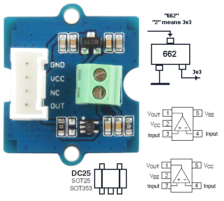 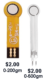 Don't
pay $15.00 for a pressure sensor. These sensors cost less than $2.00
(posted) and they are available from 200gm to 20kgm sensing range. Don't
pay $15.00 for a pressure sensor. These sensors cost less than $2.00
(posted) and they are available from 200gm to 20kgm sensing range. We are just going to test these sensors and provide a readout on LEDs that blink to indicate the value in grams. You can then get the experience of interfacing them to a display circuit. But we are mainly concerned with their suitability for various different applications and how they perform. This pressure sensor contains a pad of resistive material that decreases in resistance when it gets squashed. There is no bending or movement of the sensor. The $2.00 (0-500gm) FORCE DETECTOR is sold on AliExpress as: DF9-40 Hi-Precise Nanometer Pressure Sensor Resistance-type Thin Film 0-500g Force Sensor. To test this FORCE DETECTOR, (also called FORCE SENSE RESISTOR -FSR) connect it to a multimeter set to HIGH OHMs. The resistance will be close to infinity when no force is applied to the pad. The resistance decreases to less than 10k when full force is applied. 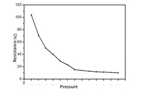 The
graph shows how the resistance decreases as pressure is applied. Connect
the sensor to 5v via a 47k or 100k resistor and measure the voltage
across it at different loads. Use a microcontroller to read the
voltage and have a "look-up" table to convert the voltage to a weight. The
graph shows how the resistance decreases as pressure is applied. Connect
the sensor to 5v via a 47k or 100k resistor and measure the voltage
across it at different loads. Use a microcontroller to read the
voltage and have a "look-up" table to convert the voltage to a weight. Here
is a circuit that buzzes when a particular pressure has been detected: |
|||||||||||||||
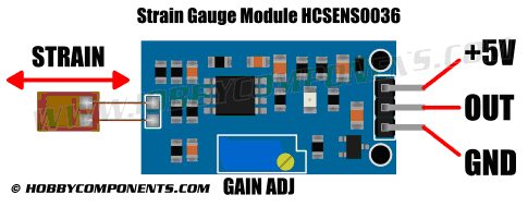
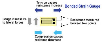
| Not in the kit | STRAIN GAUGE This sensor is a very thin plastic sheet that is actually flexible printed circuit board material. A very thin track has been etched and because the track is so thin and long, it has a resistance of about 350 ohms. When you bend the sheet, the thin track gets stretched and it gets longer. The result is the resistance increases. But this increase is very small and you need a very sensitive circuit to pick up the increase. That's what the module does, with its very-high-gain amplifier. You will be able to experiment with this cell and glue it to a plastic ruler and when the ruler rests over the edge of a bench and is loaded, it will bend slightly and the reading from the strain gauge will change. Some weighing scales use this principle because the strain gauge does not get touched or damaged and you can measure 1,000kgm or more. 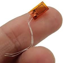 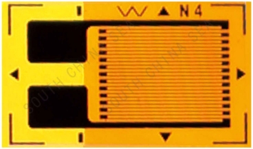 There are 26 strands on this sensor 3.1mm long = 80mm The resistance is 250 ohms. The resistance will increase by a few ohms (less than 5 ohms) when it is stretched and reduce by a small amount when it is compressed. The best glue is clear nail polish as it is completely rigid. 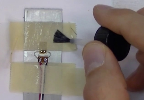 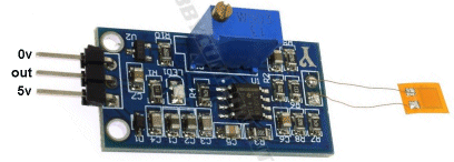
The individual Strain Gauges and the Strain
Gauge module is available on AliExpress for 50 cents each and the module
for less than $3.00 incl postage. You have to look around for the lowest
price. These are normally $6.00 plus postage. |
|||||||||||||||
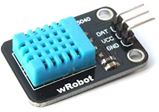 There
are 3 different pinouts for the Humidity sensor. This sensor has
to be TURNED OVER so that the data pin is the first pin.
There
are 3 different pinouts for the Humidity sensor. This sensor has
to be TURNED OVER so that the data pin is the first pin. 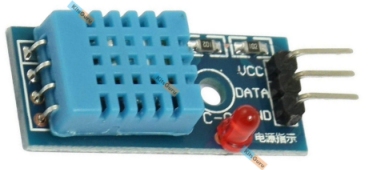 This
module needs an extension lead with data and Vcc lines crossed over.
This
module needs an extension lead with data and Vcc lines crossed over.
 This
module needs an extension lead with data and Vcc lines crossed over
and it has to be "turned over" to match the module above..
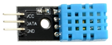
This
module needs an extension lead with data and Vcc lines crossed over
and it has to be "turned over" to match the module above..
 This
module is available from another supplier with the heading on
eBay::
This
module is available from another supplier with the heading on
eBay::
 You
have to be careful and read the legend on the PC board to get the exact
pin-out for the device you are connecting to the Testing Module.
You
have to be careful and read the legend on the PC board to get the exact
pin-out for the device you are connecting to the Testing Module. 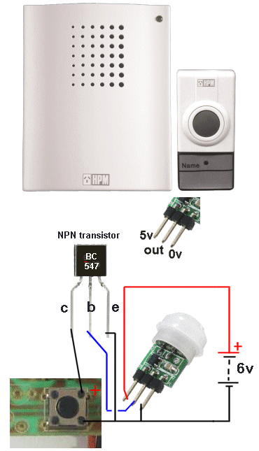
 You
can also detect human movement with a RADAR DETECTOR module for $2.00
You
can also detect human movement with a RADAR DETECTOR module for $2.00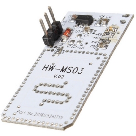 This
particular module (HW-MS03)costs $3.00 and is almost identical to the one above.
This
particular module (HW-MS03)costs $3.00 and is almost identical to the one above. 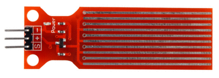
 The onboard microcontroller
will update the reading, less than every second.
The onboard microcontroller
will update the reading, less than every second. 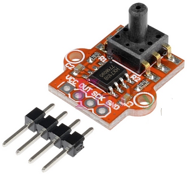
 If
you need to send a 5v signal to a module that is operating on a 3.3v
supply, you will need to add a resistor, such as 10k to the line
so the 5v signal will not damage the input of the 3.3v device and at the
same time, the 5v line will not be damaged.
If
you need to send a 5v signal to a module that is operating on a 3.3v
supply, you will need to add a resistor, such as 10k to the line
so the 5v signal will not damage the input of the 3.3v device and at the
same time, the 5v line will not be damaged. 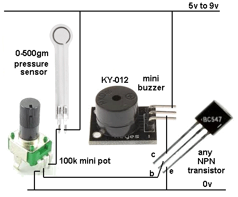
23-10-2018
INTERFACING
When you have tested all the modules (or at least most of
them), you will have some idea of what
they do.
Connecting them to another circuit or module is called INTERFACING.
Depending on what you want to do, you will be able to see it is quite
easy to connect some of them to a LED or speaker or even a relay.
The next stage will be to work out if the module is
sensitive enough for your application and/or if the LEDs are
bright enough.
Our test only puts 2mA - 5mA through the LEDs (such as the bi-coloured
and tri-coloured LEDs). The current can be
increased to 17mA and the illumination will be considerably brighter.
But to test a tri-coloured LED, a very low current is needed so you can
see the individual LEDs. In addition, a high-bright LED will "wash-out"
your eyes and you will be temporarily blind.
The Arduino Module is an "over-kill" for many of the modules as you
don't need very much additional circuitry to get them working. In addition, you may need a
number of simple circuits if you are going to use more than 2 or 3
modules in a project and the coding for the Arduino module is based
around a single module at a time.
There are many other Arduino modules on the web and some are very complex and very
expensive.
This article is just to get you started and shows how you can use these
modules individually with very simple additional circuitry, generally
obviating (doing away with) the need for the Arduino module.
That's why you need to test them first and find out their capabilities.
Some modules are quite useless and others are difficult to interface
while others can be replaced with a much simpler arrangement.
Talking Electronics has many circuits and idea (and development PC boards
-
also called PROTOTYPING PC BOARD)
to help you in this area.
Go to TalkingElectronics.com website and look at the enormous range of
circuits, kits and ideas.
WHY THESE MODULES ARE SO IMPORTANT
These modules give you an understanding of how a module (in this case
the modules are called SENSORS) works and how effective it is in doing a particular task.
After you have worked with these 50 modules, you will be able to bundle
them up and take them to your next job interview and show your knowledge
and capabilities - working with DETECTION DEVICES.
Getting things to work is the hardest part of electronics and it is the
INTERFACING that takes the time.
You will find this out very quickly when writing a microcontroller
program and try to detect a particular event such as an input from a
monitoring device or even a switch.
When you have done this and de-bugged the problems, you can say you
are ready to add these things to your list of capabilities.
No-one is going to hire you unless your can "fit-in" from DAY ONE and
Talking Electronics has helped many electronics engineers to be
successful, over the past 30 years.
We have had lots of emails to say how much they learnt from Talking
Electronics magazine and the kits we have produced and the projects we
have presented and the only way to get confidence in this field is
to have knowledge "under your belt" before you go for an
interview.
These modules have proven to be very interesting, sending off to 15 different
suppliers on eBay and AliExpress and testing $1.00 modules (that you could
not make for $1.00 !!!!) Take advantage of the low price and get a
great deal of understanding in this very important area.
The Testing Module tests almost everything and is much quicker than
any other way and shows how well they perform and how to interface
them to other circuitry.
Now's the time to start.
WHAT DID YOU LEARN?
One of the
biggest realisations you will get from testing these modules, is the
fact that there are many ways to: "skin a cat."
There are many ways to get a result and you will find some are very
expensive, while others are simple and cheap.
But one thing underlying the choice is to select a sensor that produces
a vary large output. A large output is easy to read and all the
disturbing factors (influencing factors) such as component tolerance, temperature drift,
surrounding interference, RF interference etc will affect the reading only very slightly.
Before you decide on any type of sensor, you should look at the types we
have covered and also search the web for additional possibilities.
Also use the web to see how other engineers have tackled the problem and
don't make things more-complex than your competition.
You will simply give them a "marketing advantage."
Simplicity is always the key-note to success and these modules will give
you a starting-point to producing a simple solution.
