|
4 Points |
|
|
| This project controls 1, 2,
3 or 4 points. It includes 4 toggle switches. LEDs show the condition of the point. The circuit includes a voltage doubler, so it will work on a voltage as low as 12vAC or 15vDC. |
Talking Electronics has designed 6 different Point Controllers using
an electrolytic to deliver a small amount of energy to a "Point Motor"
to change the position of the rails.
Many of the "old style" points have two solenoids to move the rails
and if these "Point Motors" are supplied with 12v for more than a few
seconds, they get very hot and melt the plastic housing.
Using an electrolytic to deliver the energy prevents anything getting hot or being
damaged.
The circuit to change a point is called a CAPACITOR DISCHARGE UNIT and
this project uses a CDU and 4 switches to operate up to 4 points.
See all the other CDU units (projects) designed by Talking Electronics
before starting this project as one of the others may be more suitable.
One of them uses an RF link to each of the points and this saves wiring.
This is handy if the point is remote from the control panel or difficult
to lay the wiring.
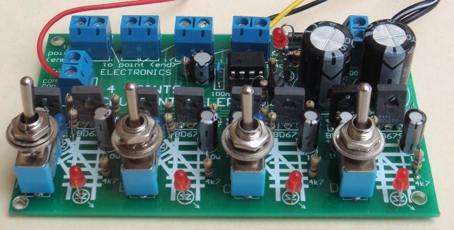
The 4-Points CDU Controller PC Board has 4 toggle switches and LEDs to indicate the position of
the point at each location.
The LEDs are on the boost voltage to show this section is working. They
also show the charging of the electrolytics and you will have to wait a
few seconds after switching a point to allow the electro's to charge to full
voltage.
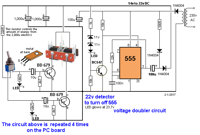
The 555 IC forms an oscillator with a 100u on the output to produce a
voltage-doubler. This allows a supply as low as 12v to charge the
electrolytics to about 20v.
The 22v zener stops the charging when the electro's
reach 22.5v by taking pin 4 of the 555 LOW via the BC547 transistor. This turns off the 555.

One 220R supplies all 4 CDU sections.
THE 22V ZENER
The 22v zener is supplied as 2 x 11v zeners.
You also get 2 x 15v zeners.
When zeners are placed in series you get a voltage equal to the addition of the two voltages.
By supplying 2 x 11v, you get 22v.
You can also get 11v + 15v = 26v or 15v + 15v = 30v.
The higher voltage (26v to 30v) will only allow the electro's to be charged to full voltage if the supply is 16v DC or 12v AC. This is because 12v AC becomes about 17v DC after it passes through the top power diode. Lower voltages may not quite reach the fully charging voltage, however this will not matter if you find the electro's have enough "punch" to operate the point when charged to 22v.
Version1 of the PCB has a single location for the 22v zener. Two zeners are needed to get 22v.
The zeners are fitted IN SERIES on the PC board. This means one zener has the black line on the body of the zener going down the top hole (that has the bar on the symbol on the board).
The other zener has the end of the zener that doesn't have the black line on the body going down the other hole. Solder them both. Now cut the leads on the top of the two zeners very short and fit a red LED with the anode above the hole marked as a cathode for the zener.
This will allow the LED to illuminate when 23.7v has been reached.
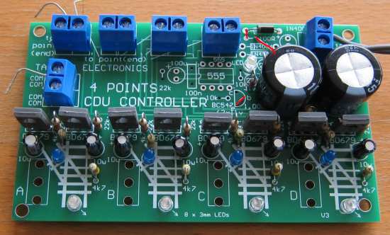
Version 2 of the PCB has separate holes for the two zeners and a location for the red LED.
THE VOLTAGE DOUBLER
The 555 section is a voltage doubler.
It does not quite double the voltage but when the input is more than 13v, we have to turn the circuit off to prevent more than 22.6v appearing on the electro's.
The terminal voltage on the electro's (the final voltage) is determined by the value of the zener.
This is simply just like a piece of steel rod. It is absent until the voltage is 22v on the electro's and it suddenly appears and as the top of the rod rises above 22v, the bottom of the rod rises too - but is is 22v lower.
At the moment, the bottom of the rod has 0v on it, but as the voltage rises above 22v, the bottom starts to rise.
As soon as the bottom rises to 0.7v, the transistor gets fully turned ON and the voltage on the collector falls to less than 0.3v. This action turns OFF the 555 and the electro's are not charged to a higher voltage.
The electro's supplied in the kit are rated a 35v and the zener can be 30v.
The circuit produces a voltage called "boost" and the 555 arrangement allows the project to be connected to a supply as low as 12v and this will allow about 20v to be delivered to the electro's.
When the project is turned ON, the two 1,000u electro's are charged via the 100R and two diodes. Suppose the supply is 12v. The two electro's will get charged to about 10.5v.
The 100u is charged when pin 3 goes low and say it charges to 10v.
When pin 3 goes HIGH the voltage on the electro is "on top" of the voltage of pin 3. Say pin 3 is 9v.
The 100u will have 9v "worth of charge" on it (in it) and this will add say about 50mV to the voltage in the two 1,000u's. The 100u will los almost all its charge.
Pin 3 will go LOW and the 100u will charge again. On each cycle the 100u delivers most of its energy to the 1,000u's.
When the 1,000's is approaching the maximum voltage, only a very small amount of the energy in the 100u will be delivered.
That's why it takes many cycles to increase to the last few volts.

One point has already been connected with the wires going to the end
terminals on the point motor and the centre wire going to the COM on the
project.
CONNECTING THE
SOLENOIDS ADDING A
PRE-VOLTAGE MODULE
4
Points 2 to
10 POINTS CDU CONTROLLER
3/1/2017
The plug-pack can be AC or DC and the project doubles the voltage to
get approx 22v
for the 2 x 1,000u electrolytics.
The stored energy in the 2 x 1,000u electro's is plenty to operate a
point
and the project reduces the amount of energy being released by
selecting the value of the 220 ohm resistor under the board.
It can be increased to 330R or higher to operate a
"stubborn point motor."
The "Point Motors" are actually solenoids. There are two solenoids
inside the plastic housing and a solenoid is simply a
coil of wire consisting of many turns. In the middle of the coil is a metal rod
(the metal must be a material that is attracted to a magnet) and when the solenoid is supplied with a voltage it produces magnetic
flux. This magnetic flux attracts the metal rod. If the metal rod is a
magnet (in other words it will pick up small nails when it is removed
from the housing), the magnetic flux is capable of attracting the rod
and/or
repelling it.
It does not matter if the rod is repelled or attracted, you only need to
know that the rod moves when voltage is applied to the ends of the coil.
This rod is called an ARMATURE. Any piece of metal that is pulled
(attracted) by an electromagnet is called an ARMATURE. This applies to a
relay, a bell and a motor. (In other types of solenoid arrangements - that control gasses and fluids
- it can also be called a plunger or
piston or "core.")
Another coil is placed at the end of the first coil and when the second
coil is activated, the rod
is pulled into the centre (middle) of the second coil.
This is how the "Point Motor" achieves "Push-Pull" activation and a
steel wire connected to the rod can be taken to the rails (called
"switch rails") to move them.
The two solenoids are wired together in series with two end wires and a
middle wire (called the "common"). This reduces 4 wires to 3.
The "common" is connected to 12v and when one of the outer wires is
connected to 0v, the steel wire from the armature pulls into the
solenoids. This voltage is now removed very quickly to prevent to
coil getting hot. When
the voltage is connected to the centre and other end wire, the
steel-wire is pushed out of the Point Motor.
This is what we call "manual activation."
Instead of connecting the voltage manually, this is what the circuit
does.
It give a pulses of energy to one of the coils and is then turned off so
the coil does not get hot. The electrolytic can now charge up for the next activation.
This timing is done by the 10u electrolytic on the base of the
Darlington transistor and the 220R feeding the switch. Increasing the
value of the 220R increases the amount of energy passed to the solenoid
and if the solenoid receives too much energy, the armature bounces
against the "end stop" and does not fully change the point. You may have
to adjust the value of the 220R to suit the type of point motor you are
using.
The first 4k7 is connected to a LED to show the setting of the point and the second 4k7 is designed to turn off the transistor
completely.
A toggle switch selects one of the two sections of the circuit to control the
activation of the point motor.
There are 4 of these circuits on the board.
The 4-Points CDU Module now comes
with a PRE-VOLTAGE module that you connect to a DC supply of 12v to 20v
and the module produces 25.5v for the 4-Points CDU Module.
Some of the components are not required on the 4-Points CDU
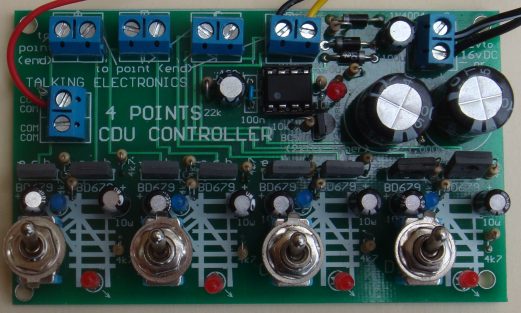
Module and the image below shows the fully constructed module with 3
jumpers highlighted in red. The top jumper is located under
the board. The 3 wires connected to the terminals have been used to test
the module.
CDU Controller
Parts List
Cost:$30.00
plus $4.50 postage
Kits
are available
1 - 100R all 0.25watt
1 - 220R
1 - 1k
16 - 4k7
2 - 10k
1 - 22k
1 - 100n monoblock capacitor
8 - 10u electrolytics
2 - 100u electrolytics
2 - 1,000u 35v electrolytics
3 - 1N4004 diodes
2 - 11v zener diodes
2 - 15v zener diodes
5 - 3mm red LEDs
4 - 3mm green LEDs (or blue)
1 - BC547 transistor
8 - BD679 Darlington transistors
1 - 555 IC
1 - 8 pin IC socket
6 - 2-way terminal blocks
1 - 20cm very fine solder
4 - toggle switches
1 - 4 Points CDU Controller PCB
A new version of this controller is now available for 2
points, 6 points, 8 points or 0 points.
The 4 points controller version above is the cheapest
for 4-points but the new version is EXPANDABLE.
All the versions have LEDs to indicate the position of
the point and a
voltage-generating circuit to allow a voltage as low as
12v AC or 16v DC.
The expandable version is also adjustable to drive
points "mildly" "normally" or "powerfully."
The 220 ohm resistor feeding the centre leg of the
toggle switch determines how quickly the electros are
discharged and this controls the amount of energy passed
to the solenoid in the point.