|
Page
11:

THE
TOUCH
PLATE

The
touch plate is the section at the end of the printed circuit board.
The first thing you must do is cut it off so it can be used for the
projects.

This
is done by cutting along the line with a hack saw or sharp knife. Some
boards have a row of small holes to make separation easier while
others have a score-line to allow the board to be "snapped
off."
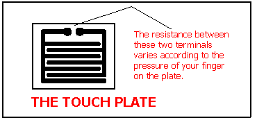
The track-work for the TOUCH PLATE looks like two interleaved combs.
It will be connected to the projects via two leads and used as a
"touch sensor plate" or "rain alarm."
If you study the tracks on the board you will find they are very close
together BUT THEY DO NOT TOUCH EACH OTHER. This is equivalent to two
long, bare wires running parallel to each other, then folded
back-and-forth to take up the least area. When you touch any part of
the plate with a finger, you touch both the tracks at the same time
and the resistance between them decreases. To understand this you will have to know a
little bit about the term RESISTANCE.
Resistance is measured in OHMs and when something is a good conductor
it has a low resistance. In other words it has only a few ohms
resistance.
When something is a bad conductor it has a high resistance. In other
words it has a resistance of many ohms, sometimes thousands of ohms or
even millions of ohms.
The resistance between the two tracks on the touch pad (when not being
touched) is many millions of ohms. When you touch the plate, the
resistance reduces to about 100,000 ohms. When you press harder, this decreases to 50,000 or 30,000 ohms.
When the plate is connected to a circuit, the change in resistance is
detected by the circuit and a certain amount of current flows. This
current is very small and the circuit amplifies this current. In one
of the projects the touch pad is used to turn on a LED. In another
project it is used to alter the flash rate of a LED and in project 5
the touch plate is used to change the tone of an oscillator.
When you press harder on the plate, the resistance decreases. This is
because more of your finger touches the tracks and more moisture comes
out of the pores of your finger. It is the MOISTURE IN YOUR FINGER
(the salts in the moisture) that causes the resistance to reduce.
The touch plate can also be used as a rain detector (experiment 5).
When a drop of water falls on the grid, it touches the two tracks and
reduces the resistance between the terminals. Pure rain water is non
conductive however as the droplets fall through the air they pick up small amounts of carbon-dioxide and other impurities and this
makes the water slightly conductive.
The interleaving grid pattern has been chosen as it effectively
multiplies the resistance of your finger, or in the case of the rain
drop, the conductivity of the rain drop by allowing a large amount of
the printed track-work to come in contact with the drop of water.
This type of pad was one of the earliest forms of touch switch and was
used in a number of electronic devices in place of a push button. It
was one of the first attempts at a vandal-proof switch or trouble-free
switch, however it suffered from one major problem. If residue was left on the pad, such as jam, butter or oil from the skin, it became
less effective.
In addition, it did not work successfully for all type of users. The
effectiveness of the pad depends on the amount of moisture in the
finger and it will not work very effectively with a very dry finger.
If your pad does not work as described in any of the experiments, try
moistening your finger slightly and see the results improve. Touch
plates have now been replaced with membrane switches in most
electronic devices. Membranes require only very slight pressure for their operation and no dirt can enter the sealed switch, but a touch
pad is a very good way to show how the resistance of your skin
changes with pressure and moisture content.
This is important because electrocution is much more severe when the
body or hand is wet or when you are pressing heavily on exposed wiring
etc. But don't worry about this in any of our experiments, the voltage
is so low that none are dangerous at all.
SUMMARY
The touch plate is similar to a variable resistor. In other words it
is a resistor in which the resistance can be altered.
The resistance of the touch pad is very high when not touched
and its resistance reduces when touched. The harder you press, the
lower the resistance between the terminals.
When used in the siren circuit, the lower resistance produces a high
tone and when used in the LED flasher circuit, the LED will flash
faster when you press hard on the plate.
|
