|
Page
18:

SIMPLE
SIREN
Build
your own Simple Siren and learn how it works
This is Project
#5 on the PC board in "5-PROJECTS"
This project is built on the
third section of the PC board, identified by "SIREN"
and "Project 5." You will notice the similarity between this
circuit and the LED FLASHER circuit from project 2. The only differences
are the LED has been removed and the 22R resistor has
been replaced by a mini speaker.
The
10u has also been replaced with a smaller value of capacitance (10n)
and this makes the circuit operate at a much higher frequency. The
result is a tone from the speaker. (If you connected the speaker to
the LED Flasher circuit you would get a "click - click -
click"
at 2 clicks per second.
This SIMPLE SIREN circuit uses components we have covered in the front of
this book and up to now you have seen how a varying current on the
base of the first transistor affects the flash rate of the circuit. Now
you will HEAR how the varying current alters the frequency at
which the circuit operates.
PARTS
LIST
1 - 1k resistor
(brown-black-red-gold)
1 - 100k resistor (brown-black-yellow-gold)
1 - 10n greencap or ceramic
1 - 47u 16v electrolytic
1 - BC 547 NPN transistor
1 - BC 557 PNP transistor
1 - 8R speaker
1 - touch plate - (from project 2)
1 - 20cm hook-up wire for speaker
1 - "5-PROJECTS"
PC Board |
HOW
THE CIRCUIT WORKS
There are many ways to explain how a circuit works and we have
presented three different approaches in this course - the voltage
approach, the current approach and the resistance approach.
Sometimes we have combined all three.
In this final project we will explain how the circuit works using the
resistance approach. We start with the touch plate. When the
touch plate is touched, the 47u electrolytic gradually charges via
the resistance of the plate. In the notes we have explained how
the touch plate works, with its resistance varying according to the pressure
of your finger.
The base of Q1 sees the voltage on the electrolytic and when it is
about .6v, the transistor starts to turn on.
Since
Q1 is directly coupled to the second transistor, Q2 turns on too. When
Q2 turns on, the resistance between its collector and emitter reduces
and allows current to flow. This causes current to flow in the
voice coil of the speaker and pulls the cone towards the magnet.
This is the first half of the cycle for the speaker.
Also connected to the collector of the PNP transistor is one end of a
10n capacitor and when one lead of the capacitor rises, the other side
rises too. (This is because it is uncharged at the moment). This has
the effect of turning on both Q1 and Q2 even harder. This action
runs around the circuit until both transistors are turned on fully.
At this point the 10n capacitor begins to charge via the base-emitter junction
of Q1 and the collector-emitter junction of Q2. When the
capacitor becomes nearly charged, the charging current reduces and
it cannot keep Q1 turned on as much and it begins to turn off slightly.
This begins to turn off Q2 and the voltage on the collector of Q2
falls. The 10n capacitor is connected to this and both ends begin to
fall and turn off Q1. This action turns both transistors off and
the voltage on the base of Q1 is below the negative rail (as explained
in Project 2).
Current through the voice coil of the speaker ceases and the cone is
released. This completes the cycle for the speaker and it's the action
of pulling the cone towards the magnet and releasing it that produces
the tone.
The charge on the capacitor is now cancelled by the current from the 100k
resistor and it begins to charge in the opposite direction so that
the voltage on the base of Q1 rises to .6v. At this point the NPN
transistor turns on again and the cycle repeats.
If the touch plate is kept touched, the tone from the circuit
gradually rises as the time taken to charge the capacitor at the
end of the cycle will be shortened. This is due to a higher
voltage being present on the electrolytic and thus a higher
current will flow through the
100k resistor to charge the capacitor faster.
Most of the explanations of how the circuits work have opened up more questions
than they answered. This is only a commencement book and future
books will elaborate on the operation of the circuits in more detail.
Even if you have only learnt the resistor colour code and got the
projects to work, you will have achieved all this book has intended
to get across.
Furthermore, if you like what you have learnt, electronics will be buzz
and a very rewarding hobby. Look out for the next books in the series.
ASSEMBLY
All the components fit on the section of the PC board marked
"SIREN." The two resistors lay flat on the board and
the other components are pushed up until they are about 3mm
(3/16") from the board. Use the layout diagram on this page
to see where they go and how they fit. Don't forget to hold each
part as you solder it to make sure it doesn't get too hot.
Now
for the assembly.
Collect the parts and lay them on the work bench.
You are now ready to start. Mark off each step as you do it.
( ) Bend the leads of the 1k resistor to 90° and push them through
the holes identified by the 1k symbol on the board and hold the
resistor while soldering it. Cut the ends of the wires with a sharp
pair of side cutters making sure you do not cut any of the solder
joint, as this may damage it.
( ) Repeat with the 100k resistor.
( ) Fit the 10n capacitor by pushing the leads through the holes until
the body of the capacitor is almost touching the board. Solder the
leads quickly so that the component does not get too hot. Cut off
the leads neatly.
( ) Fit the 47u electrolytic with the negative lead close to the edge
of the board and the positive lead down the hole marked with a
"+."
( ) Fit the PNP transistor at the position marked on the board with
a "D" symbol, making sure the leads are correct for the
transistor you are fitting.
( ) Fit the NPN transistor in the same way.
( ) Connect the touch plate to the holes marked on the board via the
two wires attached to it, (you may have to remove it from the other
section of the board.)
( ) Fit the speaker wires to the speaker and solder the other ends to
the board.
The project is now complete.
Slide the power switch on and the touch the touch plate. After a short while
the siren will start up. Keep your finger on the touch plate and
the tone will increase. You can regulate the tone by pressing lightly
or with more force.
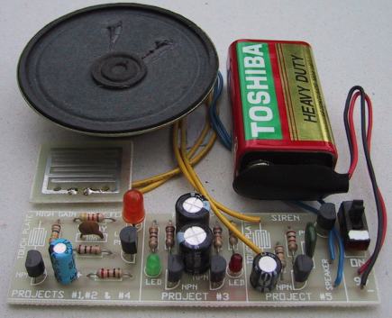
The Siren components fitted to the
board.
Touch the Touch-Plate to increase the Siren tone
release to decrease tone.
IF THE
CIRCUIT DOESN'T WORK
If the circuit doesn't work, you should go over the construction notes again,
making sure you have not left anything off the board. Look at the
solder side of the board and make sure no joints have been left
unsoldered.
If the other projects are flashing when the power is switched on, the
battery will be ok. This circuit will work down to a voltage of 3-4v,
so it is not voltage critical.
Look at the speaker to make sure the leads are soldered correctly. The
other major cause of a mistake is the transistors. Make sure they are
the correct types for both the NPN and PNP positions and make sure
they have been fitted correctly.
Get someone else to check this for you as it is difficult to check your
own work.
If you have held the transistors while soldering, they will not be damaged,
but if you had to let go, they could be damaged.
Buy two more as "spare parts" and fit them to the board.
In later pages we will show how to test the circuit using a multimeter and
other test equipment but we have not covered these yet and the only
thing you can do is visually inspect the board for correct parts placement
and make sure the soldering is neat.
If you have made a mess of your PC board, it would be a cheap price to
buy another board (or book), get another kit of components and start
again.
This time you will make a much neater job and learn a lot in the
process.
You really have to feel you have been successful with this e-book before you
should go on to the next in the series.
INCREASING THE VOLUME
The
output volume of the siren can be increased by
adding 4 components. The 10R and BC338 create a
buffer stage to increase the current.
The BC557 is not capable of delivering more than
about 50 to 100mA and the sound is not very loud.
By adding a BC338, the current to the speaker will
be increased and the output volume will increase.
These 4 components are available for FREE by
emailing Colin
Mitchell at Talking Electronics and they are
soldered to a small matrix board and added to the
project.
WHAT
HAVE YOU LEARNT?
These are the areas we have covered in this e-book: Tick those you have understood:
( ) Recognising components such as transistors, resistors, capacitors.
( ) Placing components correctly on a Printed circuit board.
( ) Soldering components neatly to a PC board.
( ) Holding components while soldering so that they do not get too hot.
( ) Understanding the concept of resistance - high resistance and low
resistance.
( ) Understanding the concept that a capacitor stores energy - it "charges
up."
( ) Understanding a speaker produces a tone by current flowing through
the voice coil then ceasing to flow and repeating the process to
produce a tone.
( ) Understanding a LED produces coloured light when current flows through
the special type of crystal it is made of. The colours are: red,
green, yellow, orange and blue.
( ) Understanding a transistor is an amplifying device with the
base as the input and the collector as the output.
( ) Understanding current flows through a circuit when it is switched on.
In the siren circuit for example, there are a number of different current
paths and a different value of current flows through each path.
You don't have to FULLY UNDERSTAND any of the concepts, just be aware that
they exist and be prepared for further study in future pages.
THE END
This completes the 5 projects.
There is a lot to be learned from the circuits in this project as they
are often used in our other projects.
You can experiment with the circuits to create different effects. By
placing a different value resistor across those on the board, you will
be able to see the effect of lowering the resistance.
Some of the capacitors can also be changed and the effect will be quite
noticeable. This is a very good way to find out the effect of
various components on the operation of the circuit.
The only page remaining is the TEST PAGE. See how much you have
learned by taking the test . . .
|