|
|

This discussion covers a number of ways to generate 5v (and up to 10v)
from 1 or 2 cells.
It also covers how to get 5v from a number of nearly flat cells and
generating a voltage from solar cells.
Every project needs a power supply. It may be a single 1.5v cell or a
3v lithium cell. It may be a 9v battery or a set of 4 cells to get
6v.
It's wonderful if you can fit a battery and everything works perfectly,
but there are lot of times when the voltage from the cells is not
exactly the correct voltage. It may be too high or just not quite
right. In addition, the voltage from a set of cells will drop as they
get older and
may create problems with reliable operation of the project.
What is needed is a REGULATED SUPPLY.
A regulated supply will deliver a fixed voltage, even though the cells
are getting flat.
Imagine if you had a 9v battery that remained 9v, instead of dropping to
8v, 7v, 6v and finally dying.
The same with a 5v supply for a microcontroller project. Four cells
produces 6v and this is too high for a micro. Adding a diode drops the
voltage to 5v4 and as the cells start to get old, the voltage drops to
less than 4v.
By adding one of our circuits, the voltage remains at 5v6 until the
cells are at the end of their life.
These are the circuits you have been wanted for a long time.
Theory on how a
POWER SUPPLY works can be found on Talking Electronics website.
![]()
CIRCUIT 1
5v3 to 10v
OUTPUT
Q1 is a current amplifier
Q2 is an oscillator
Q3 is a signal inverter
Q4 is the output voltage detector
This circuit converts a 3v supply to 9v. It can take the
place of a 9v battery and perform better and cost less.
The biggest problem with a 9v battery is the small amount of energy
it contains.
This has been improved recently with the introduction of alkaline and
lithium cells but you are paying a high price for theses types of
batteries.
The cheapest battery contains manganese dioxide or ordinary "dry"
cells, so called because they did not spill when tipped over.
Customers thought the cell was "dry" and this is how it got its
name.
But the problem with this type of cell is the voltage rapidly falls
to less than 1.2v per cell and with 6 cells in series, this becomes
about 7v.
As the voltage drops to any device such as a radio or amplifier, the
current also drops and since the output power is a combination of
these two, the performance drops appreciably.
Imagine if you could provide a constant 9v. The output of your
project would remain high and the performance could be guaranteed.
This circuit is the answer.
It provides a regulated output of 9v from two AA or AAA cells and
costs less than any of the 9v batteries on the market.
The only thing we cannot deliver is a very high current. Some of the
lithium and alkaline batteries will deliver over 2amp for short
periods of time and we cannot compete with this performance.
However we can compete with a standard 9v battery and deliver a
constant current of up to 70mA with a voltage drop of less than
60mV.
9v batteries are rated a 330mAh at a discharge of 2mA. When the
current increases to 50mA, the rating is 200mAh and at 100mA the
rating is less than 100mAh. By using AA cells we can compete very
favourably with these figures and provide a constant 9v output.
The clever part of the circuit is the current amplifying transistor
driving the base of the second transistor.
This transistor allows the circuit to consume less than 10mA when
idling (quiescent current) and draws over 250mA when delivering 70mA
to the load. Without this transistor, the quiescent current would be
30mA.
HOW THE CIRCUIT WORKS
The circuit starts via the current supplied by the 100k turning on
the third transistor via its base.
This turns on the first transistor and supplies current to the second
transistor to turn it ON.
The voltage on the collector of Q2 drops and this pulls the 330p towards
the 0v rail. This turns on the first transistor more and the two
transistors keep turning on more and more until they cannot turn on any
harder. The 330p is charging during this time and it continues to charge
and as it becomes more-charged, the charging-current falls and this
turns off the first transistor slightly.
This action turns off the second transistor slightly and the voltage on
the right-side of the 330p rises and this reduces the charging current
through the first transistor and very soon the first transistor is
turned off more. This action turns off the second transistor.
The current through the inductor stops and the magnetic flux collapses
and produces a voltage in the opposite direction.
This voltage flows through the 1N4148 diode and charges the 100u
electrolytic. It also charges the 330p in the opposite direction via the
33k. When the high voltage from the inductor decays, the voltage on the
right-hand plate of the 330p drops and this lowers the left-hand plate.
This action turns on the first transistor and the two transistors begin
to turn on again, assisted by the presence of the 33k.
5v to 10v REGULATED SUPPLY
As the voltage on the 100u increases, the
voltage at the join of the 1k and 5k6 increases and when it reaches
0.65v, the fourth transistor begins to turn on. This action turns off
the third transistor slightly and this has the effect of making the 33k
a larger value.
This means the 330p is not charged as much during part of the cycle and
during the next part of the cycle it does not turn on the first
transistor as much.
This means the two transistors do not turn on as hard and thus the
output voltage does not rise above a particular value.
This is how an exact voltage is produced on the output rail. It is
accurately set by adjusting the 10k pot.
When a load is applied, the output voltage decreases and turns off Q4 slightly.
This turns on Q3 slightly and allows the 330p to charge slightly
more so that the two oscillator transistors "work harder."
The end result is more energy
delivered by the inductor and the voltage is restored.
The output voltage can be maintained up to an output current of
about 70mA. This is as much energy as the inductor can deliver.
After this, the voltage drops off slightly when a higher current is
required.
The circuit can be set to a minimum of 5v and a maximum of 10v
via the pot.
CONSTRUCTION
The core of the inductor (transformer) is obtained from a 10mH inductor
but any core of the same size can be used.
Remove the original winding.
Wind 70 turns of 0.25mm wire (or any near size) enamelled wire to
fill the bobbin and solder the ends to the two pins connected to the
bobbin.
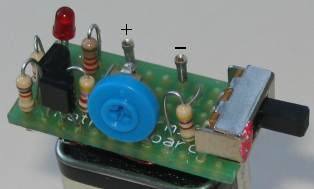
The components can be assembled on a small piece of matrix board.
![]()
CIRCUIT 2
5v
REGULATED SUPPLY FROM 3v
This circuit will produce
a 5v regulated output from 2 cells (3v). The output current is limited
to 50mA but will be ideal for many microcontroller circuits.
The output voltage is set to 5v by the 3k9 and 560R resistors, making up
a voltage divider network.
![]()
CIRCUIT 3
5v FROM OLD CELLS
This circuit takes the place of a 78L05
3-terminal regulator. It produces a constant 5v @ 100mA. You can use any old
cells and get the last of their energy. Use an 8-cell holder. The voltage from 8
old cells will be about 10v and the circuit will operate down to about 7.5v. The
regulation is very good at 10v, only dropping about 10mV for 100mA current flow
(the 78L05 has 1mV drop). As the voltage drops, the output drops from 5v on
no-load to 4.8v and 4.6v on 100mA current-flow. The pot can be adjusted to
compensate for the voltage-drop.
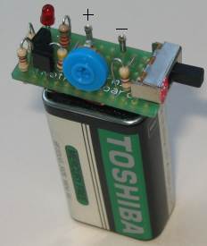
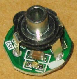
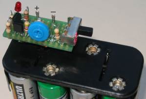 The regulator connected to a 12v battery pack
|
|
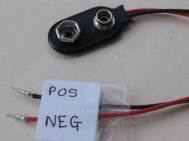
The battery snap plugs into the pins on the 5v regulator board with the red lead going to the negative output of the board as the battery snap is now DELIVERING voltage to the circuit you are powering. A close-up of the regulator module |
|
 |
![]()
CIRCUIT 4
1.5v to 5v PHONE CHARGER
Sometimes it is better to use
something that is already available, rather than trying to re-invent the wheel.
This is certainly the case with this project. You could not buy the components
for the cost of the complete phone charger and extension leads.
The circuit will deliver 70mA at 5v and if a higher current is drawn, the
voltage drops slightly.
These chargers were originally priced at $30.00 !! Contact
Talking Electronics for the supplier.
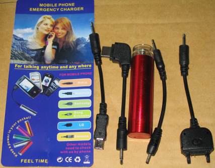
The AA case and 4 adapter leads - cost: $3.00!!
The LED and 1u capacitor can be clearly seen in this
photo.
![]()
POWER SUPPLIES - FIXED
A simple power supply can be made with a component called a "3-pin regulator or 3-terminal regulator" It will provide a very low ripple output (about 4mV to 10mV provided electrolytics are on the input and output.
The diagram above shows how to connect a regulator to create a power supply. The 7805 regulators can handle 100mA, 500mA and 1 amp, and produce an output of 5v, as shown.
These regulators are called linear regulators and drop about 4v across them - minimum. If the current flow is 1 amp, 4watts of heat must be dissipated via a large heatsink. If the output is 5v and input 12v, 7volts will be dropped across the regulator and 7watts must be dissipated.
FIXED POWER SUPPLIES USING 5v REGULATOR
78L05 Surface mount 5v 100mA Regulator
![]()
CIRCUIT
6
POWER SUPPLIES - ADJUSTABLE
The LM317 regulators are adjustable and
produce an output from 1.25 to about 35v. The LM317T regulator will deliver up
to 1.5amp.
ADJUSTABLE POWER SUPPLIES USING REGULATOR
![]()
CIRCUIT
7
POWER SUPPLIES - ADJUSTABLE using 7805
The 7805 range of regulators are called "fixed regulators"
but they can be turned into adjustable regulators by "jacking-up" their output
voltage. For a 5v regulator, the output can be 5v to 30v.
ADJUSTABLE POWER SUPPLIES USING 5v REGULATOR
![]()
CIRCUIT
8
POWER SUPPLIES - ADJUSTABLE from 0v
The LM317 regulator is adjustable from
1.25 to about 35v. To make the output 0v to 35v, two power diodes are placed as
shown in the circuit. Approx 0.6v is dropped across each diode and this is where
the 1.25v is "lost."

ADJUSTABLE from 0v USING 2 DIODES
![]()
CIRCUIT
9
POWER SUPPLY TO DRIVE A WHITE LED
A white LED requires about 3.6v to
illuminate and this circuit will produce very good illumination from a single
cell:
|
Type: |
Gain: |
Vbe |
Vce |
Current |
Case |
|
|
2SC3279 |
NPN |
140 to |
0.75v |
10v |
2amp |
|
|
BC337 |
NPN |
60 |
0.7v |
45v |
800mA |
|
|
BC547 |
NPN |
70 |
0.7v |
45v |
100mA |
|
|
Transistor Specifications |
||||||
![]()
CIRCUIT 10
5v Regulated Solar
Power Supply
This project uses the
1.2v rechargeable battery and solar panel from a
Solar Garden Light. These lights can be bought for less than $5.00 in most
$2.00 shops or similar shops that sell general household items.
We are also using the housing for this project as we could not buy the case,
battery and panel for $5.00 in an electronics shop.
It is incredible that a solar panel, rechargeable battery and plastic housing
can be bought for less than $5.00!
We have already described the operation of the
Solar Circuit, but unfortunately it cannot be used to generate a voltage
higher than about 4v, so a new design had to be created. The circuit we have
designed is shown above and provides a regulated 5v output @ 10mA. If a higher
current is drawn, the output voltage will drop. At 15mA, the output voltage
drops to 4v.
This supply has been specially designed for a microcontroller project, but it
will also work for circuits such as amplifiers, FM transmitters etc.
All the components and PC
board: $11.00
0.5v @ 200mA solar cells
$2.50 each
0.5v @ 100mA solar cells
$1.50 each
Order the kit and/or solar
cells from Talking Electronics
5v Regulated Solar Power Supply
Circuit
![]()
CIRCUIT 11
5v from a Hand Cranked
Generator
When the handle is
turned fairly quickly, the output of the motor produces a maximum of 5.5v and
has a current under short-circuit conditions of about 400mA. This project is
fully described
HERE and shows how to increase the voltage of the generator by adding 100
turns to each pole of the generator and this will
increase its charging current to a 3.6v Li Ion battery.
The diode and LED connected
to the generator

Wind-up Torch/Radio
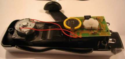
THE HAND-CRANKED TORCH - charging
current 175mA
(after the modification)
Close-up of the 3.6v Li Ion 450mAhr
cell
![]()
29-3-2010