|
5x7 Display
PROGRAMMING
STARTS
HERE Page 1

REMINDER:
These are the items you need:
- the 5x7 Display (fully
built),
- a 6v battery,
- an interface cable
- a computer.
The first 6 experiments are on:
"Experiments Page 1." (Turning a LED on, Flashing a LED, Scanning Up,
Scanning up/down, Switch Debounce, Reaction Game - Hit the middle LED)
Experiments 7, 8, 9 are on:
"Experiments Page 2." (shifting columns of LEDs left/right back/forth)
Experiments 10, 11 are on:
"Experiments Page 3." (Start/Stop action via switch, Elevator display)
Experiment 12 is on:
"Experiments Page 4." (TE Running Sign)
Experiments 13, 14 are on:
"Experiments Page 5." (Single Digit Up Counter, Two digit Up Counter)
Experiments 15, 15a, 16 are on:
"Experiments Page 6." (5 Digit Up Counter, 5 Digit Up Counter with reset, Two digit Up/Down Counter)
Experiments 17, 18, 19 are on:
"Experiments Page 7." (3 Experiments on Animation - Wipe Up etc.)
Experiments 20, 21, 22 are on:
"Experiments Page 8." (3 more Animation including Wipe Down, Slash and
Splash)
Experiments 23, 24, 25 are on:
"Experiments Page 9." (Display after button press, Start/stop Splash,
"Bull's Eye" A "Hit-the-LED" game)
Experiment 26 is on:
"Experiments Page 10." (LED Dice)
Experiments 27, 28 are on:
"Experiments Page 11." (LED Dice with Sound-1, LED Dice with Sound-2)
The Piezo experiments are as follows:
Experiments 1P, 2P, 3P, 4P are on Piezo
Experiments Page 1 (Making a Tone, Producing a beep, Beep
after button A, B and C, Hee Haw Siren)
Experiments 5P, 6P, 7P, 8P are on Piezo
Experiments Page 2 (Calling Hee Haw Routine, Making a Note,
Creating a Scale, Creating a Tune)

|
How the routines in the
5x7 Display
work.
|
Some of the routines in
the experiments for the 5x7 Display look
very simple but a lot of thought has gone into producing them.
The art to producing a good routine is to make it look simple as this will
make it easy to follow and easy to trouble-shoot, if something goes wrong. The delay routine is a typical example. It can
be laid out using simple-to-follow instructions or complex instructions. Let's not worry about the complex approach, our aim is to show
how easy it is to program the PIC chip.
The first routine we will cover, is:
THE DELAY
The microcontroller normally advances down the program, carrying out
instructions, one at a time, unless it reaches an instruction to take it to another
location.
In the simplest delay routine below, the micro will be sent to the Delay
routine and carry out the first instruction DECFSZ 1Ah,1. This instruction
decrements file 1A (the ,1 tells the micro to place the result in file 1A) and if the result is NOT ZERO, the micro advances to
the next instruction that tells the micro to go back to the label
"Delay." In other words the micro loops from the GOTO instruction
to Delay until file 1A is zero. When 1A is zero, the micro "jumps
over" GOTO Delay and carries out the instruction RETURN.
Normally, an instruction such as MOVLW xxx is placed before the first
instruction in the delay routine below to load file 1A with a value for
decrementing. If you want the delay routine to perform less than FF loops,
file 1A must be pre-loaded. If it is not pre-loaded, the random value
(called the junk value) in 1A
will be used. When the micro is first turned on, file 1A will contain a
random value. But after the delay is executed, file 1A will contain
00.
When the delay routine is executed the second time, it will produce FF
loops. The reason is file 1A is first decremented before the "skip if
zero" part of the instruction is executed and thus it "rolls over" to FF
when the "skip if zero" is performed.
Recap: If file 1A is not zero when the delay is executed on the first
occasion, it will be 00 after the first use of the delay routine and thus
the second time the delay routine is used, it will produce the longest delay.
Delay DECFSZ 1Ah,1
GOTO Delay
RETURN
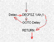
The animation below goes
over this again: The micro enters the 3-line
"Delay" sub-routine
and carries out the
first instruction. It then advances to GOTO Delay where the micro is told to
go to the label "Delay." It does this until file 1A is zero and
then the instruction DECFSZ1 Ah,1 causes the micro to jump over GOTO Delay
and execute RETURN.
The duration of the delay above can be worked out as each instruction
takes 1 microsecond except when the instruction sends the micro to another
location.
Delay DECFSZ 1Ah,1
1 microsecond (2
microseconds when file 1A is zero)
GOTO Delay
2 microseconds
RETURN
2 microseconds
The duration of the delay above is: (255
x 3)(for decrementing file1A) + 2(when file 1A is zero) + 2(for RETURN) = 769
microseconds.
If you require less than 769 microseconds,
file 1A can be loaded with a value (this is called pre-loading). For
example, if about 300 microseconds is required, file 1A must be loaded with
100, and in hexadecimal, this is 64h.
Delay MOVLW 64h
MOVWF 1Ah
Delay1 DECFSZ 1Ah,1
GOTO Delay1
RETURN
Delays are used
for many different purposes. An external chip may need to be reset, then
clocked. A delay of a few microseconds may be needed to give the chip time
to carry out the first operation before it can be clocked. A very short
delay can be created with NOP's. Each NOP takes one microsecond and can be
included in the program thus:
NOP
NOP
NOP
NOP If
a delay is required so that a LED can be viewed on a screen, for example,
the delay will have to be long enough for the human eye to view the
LED. This
requires a longer delay than can be created with a single file - a single
file can produce a delay of approx 800 microseconds. This is not long enough
for the human eye to view a display. The minimum viewing time is about
100,000 microseconds. To do this we need to decrement two or more files. If we take the example of two files,
it is no use placing one file AFTER the other as this will only create a
delay double the time of a single file. We must place the files so that they
are NESTED, with one file in the centre and the other surrounding the
central file. The result is a delay equal to the MULTIPLICATION of the two
files. In other words, a two-file sub-routine will create a delay equal to
256 times the delay of a single file. If we have a three-file sub-routine,
the result will be 256 x 256 x the delay of a single file. With a two-file
sub-routine we can create a delay long enough for the human eye to view an
illuminated LED. So, let's look at a two-file delay.
The two-file delay below is the simplest (because the files are not pre-loaded) and it will create the
longest delay as the two files enter
the sub-routine containing "00." The order of the files does
not matter in this sub-routine as both are fully decremented. File 1A is
decremented first and when it is zero, the micro decrements files 1B and
goes back to decrementing file 1A again. This continues 256 times until file
1B is zero, and the micro exits the Delay sub-routine and RETURNs to where
it came from, in the program.
This means the micro decrements file 1A 256 x 255 times and each
decrement takes 3 microseconds.
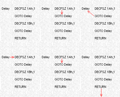
This animation shows
how the micro loops through the first two instructions
until file 1A is zero. It then "jumps" GOTO Delay and
carries out DECFSZ 1Bh,1 Instruction. If file 1B is NOT ZERO,
the micro carries out GOTO Delay and repeats the above until
file 1A is zero. This sequence continues until file 1B is zero and the
RETURN instruction is executed.
Suppose you want a
shorter delay routine than the one above, but longer than a single-file
delay. To do this, file 1B is loaded with
a value. This is called pre-loading. The delay routine becomes:
Delay MOVLW
3Ch ;Any hex value can be
loaded into file 1B
MOVWF 1Bh
Delay1 DECFSZ 1Ah,1
GOTO Delay1
DECFSZ 1Bh,1
GOTO Delay1
RETURN
A 3-FILE DELAY
For longer delays, a
three-file sub-routine is needed.
Note: We have loaded file 1A with the value 3. The last file in the
sub-routine is pre-loaded with a value if you want to adjust the duration of
the delay. It is only the last file in the sub-routine that is decremented
ONCE. All the other files are decremented 256 times (or 256x256) during the execution of
the sub-routine and cannot be pre-loaded (see below for pre-loading). Loading file 1A with 00 produces
the longest delay as it is decremented first, then tested.
Delay
MOVLW
03
MOVWF 1Ah
Delay1 DECFSZ 1Bh,1
GOTO Delay1
DECFSZ 1Ch,1
GOTO Delay1
DECFSZ 1Ah,1
GOTO Delay1
RETURN
The biggest mistake with creating a delay is sending
the micro back to a label that reloads a file and prevents the micro getting
out of the delay. For instance, the following delay will not work. Can you
spot the mistake?
Delay
MOVLW 03
;This delay will not work
MOVWF 1Ah
;Can you spot the mistake?
Delay1 DECFSZ 1Bh,1
GOTO Delay1
DECFSZ 1Ch,1
GOTO Delay1
DECFSZ 1Ah,1
GOTO
Delay
RETURN
The last GOTO instruction sends the micro to the Delay label and this
re-loads file 1A with 03 and thus the file contains 03, 02, 03, 02, 03, 02 etc. It should be GOTO Delay1. A simple mistake like this will make the
difference between a program working or not working. The micro doesn't
make a mistake. It's only humans that make a mistake. It's best to copy and paste sub-routines from working
programs to prevent mistakes like this.
We have a section called LIBRARY
OF ROUTINES where you can access routines and use them in your own
projects.
If you are having trouble getting a
program to work, one solution is to
remove the
last routine you created. But
rather than remove it
completely and have to re-type it, it can be "removed" by putting
a
delimiter at the beginning of
each
line and
the assembler will ignore the instruction, thus:
;Delay
MOVLW 03 ;None
of these instructions will be assembled
;MOVWF 1Ah
;because the
delimiter has been placed at the beginning of the line
;Delay1 DECFSZ 1Bh,1
;GOTO Delay1
;You can simply remove the delimiter when the fault has been
fixed
;DECFSZ 1Ch,1
;GOTO Delay1
;DECFSZ 1Ah,1
;GOTO Delay
;Make sure ALL LINES have the delimiter at the
beginning
of the line!
;RETURN
An accurate delay can be
produced by loading either or both files with a value and NOPs included to adjust the delay to an exact length of time.
For more
information on delays see:
LIBRARY
OF ROUTINES.
An accurate 1/10th second delay can be produced with two files as follows:
1/10 sec delay =
100,000uS = 100,000 machine cycles:
Delay
MOVLW 63h
;99 loops
MOVWF 1B
DelA MOVLW C9
;201 loops
MOVWF 1A
DelB NOP
;This is the inner loop
NOP
;This is the inner loop
DECFSZ 1A
;This is the inner loop
GOTO DelB
;This is the inner loop
NOP
DECFSZ 1B
GOTO DelA
RETURN
The inner loop takes 5uS NOP(1), NOP(1), DECFSZ(1), GOTO(2) for 200 loops and on loop 201, the instructions are: NOP(1), NOP(1), DECFSZ(2), NOP(1), DECFSZ(1), GOTO(2), MOVLW(1),
MOVWF(1). This is repeated 98 times and on the 99th time, the inner loop is executed 200x5uS then NOP, NOP, DECFSZ(2), NOP, DECFSZ(2), RETURN(2).
The total number of uS = 4 + 98(200x5 + 10) + 200x5 + 9 = 99,993uS
You can add 7 NOP's at the end to produce 100,000uS if needed.
SUMMARY
The maximum delay with a single file is about 1/1,000th
of a second.
The maximum delay with 2 files is about 250mS (1/4 of a second)
The maximum delay with 3 files is about 60 seconds.
TONES, NOTES AND TUNES - "SOUNDS"
These are all the same thing to a programmer. The only difference is the
accuracy of the sound being produced.
All sounds are produced by toggling a line. The only thing a microprocessor
can do is turn a line ON and OFF. As we know, a sound is a very complex
waveform and turning a line on and off produce a square wave. This is one of
the harshest sounds to be produced and the only way to modify the waveform
from the micro is to add wave-shaping circuitry. The simplest wave-shaping
circuitry uses a capacitor and resistor network and this can very easily be
incorporated into a design.
Another way to improve the tone of the sound is to deliver variable width
pulses. This causes the cone of the speaker to move in and out in small increments and
it "evens-out" the pulses into a smooth "gliding action" very
similar to a curvy waveform. The result is a much milder waveform and sounds
like ringing bells at a railway crossing can be produced.
For the moment we will cover the elements of producing a sound by toggling
an output line.
The diagrams below show how to connect a piezo diaphragm and speaker to an
output line.
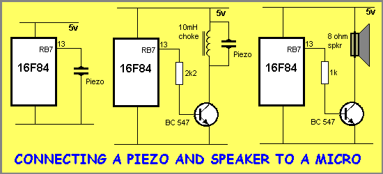
The piezo diaphragm can be connected directly as it does not require any
current to drive it (it is voltage driven) but a speaker requires current to
drive it and thus a buffer transistor is needed. Connecting a piezo
directly to the output of a micro does not produce a very loud sound as the
voltage-swing will only be about 5v. To increase the voltage across the
piezo, a choke can be added. The collapsing voltage from the choke will be
as high as 100v (the BC 547 transistor will zener at about 45-65v and limit
the waveform) and thus the volume from the piezo will be greatly
increased. The choke and piezo make a TUNED
CIRCUIT that actually improves the quality of the sound while increasing
the volume. This arrangement requires a small amount of current and must be
driven via a buffer transistor. The high voltage produced by the circuit
also requires it to be separate from the PIC drive-line.
Circuits 2 and 3 must be turned off when not required as they draw a very
high current when in the ON state. This means the program must end with RB7
LOW. If the program is toggling the output line, an instruction to BCF must be
included to make sure the line goes LOW.
A TONE
The simplest program
to produce a note or tone from a piezo (or speaker) is shown below:
Tone MOVLW
80h ;To toggle the piezo on line
RB7
XORWF 06,1 ;Toggle the piezo line
Delay DECFSZ 1Ah,1 ;Short delay
GOTO Delay
GOTO Tone ;Repeat the
sequence
If the piezo is driven by a driver transistor, the output
of the microcontroller must be turned off before leaving the
sub-routine. The routine below has this feature. Both routines produce the
same tone as the frequency for the tone is determined by the value of the
Delay. In both cases the delay is decrementing a single file.
Tone1
BSF 06,7
;this is the piezo line. Turn it ON
CALL
Delay ;Call Delay
BCF
06,7
;Turn OFF the piezo
CALL
Delay1 ;Call the delay
below
GOTO
Tone1 ;Repeat the routine
Delay1 DECFSZ 1Ah,1 ;Delay
for tone
GOTO
Delay1
Both the routines above produce a constant sound and do not stop.
The second routine can be CALLed from another routine by using the
instruction: CALL Tone1Tone1 BSF 06,7
;this is the piezo line. Turn it ON
CALL
Delay ;Call Delay
BCF
06,7
;Turn OFF the piezo
CALL
Delay1 ;Call the delay
below
RETURN
Delay1 DECFSZ 1Ah,1 ;Delay
for tone
GOTO
Delay1 The only problem is, the routine above
only produces one cycle of the tone. In other words it only pushes the
diaphragm IN and OUT once and no sound will be detected.
The routine must be repeated a number of times to produce a tone. The
routine below does this.
To call the Beep-Short routine, use the instruction: CALL Beep-S
Beep-S
MOVLW
40h
;The duration of the beep (64 loops)
MOVWF
14h
;The loop file
BpA MOVLW
80h ;The
duration of the High and Low
MOVWF 15h
BpB DECFSZ 15h,1
GOTO BpB
MOVLW
80h
;To toggle RB7
XORWF
06,1
;Toggle RB7
DECFSZ 14h,1
GOTO BpA
RETURN
BEEP. . . BEEP . . . BEEP
One of the clever diagnostic tools we have included in the
LIBRARY OF
ROUTINES is the BEEP routine. It can be placed anywhere in your program (say
directly after "setUp" or if a table is present, after the table)
and called via the instruction: GOTO Beep1.
This routine is designed to help you locate faults in a program. The biggest
problem is trying to work out how far the micro has progressed through
a program or routine and by placing GOTO Beep1 at any location in a program,
you will get a beep . . beep . . beep if the micro gets to the GOTO
Beep1 instruction.
Simulators, emulator and single-stepping programs cannot find all the
"bugs" or problems in your programs because they do not go through
the delay routines fully and do not take into account the condition of an
input line. The only way to hunt-down a problem is with this beep
routine.
At the beginning of memory, after Tables, put:
Beep1
CALL Beep
CALL BeepDel
GOTO Beep1>
Beep
MOVLW
40h
;The duration of the beep
MOVWF 14h
;The loop file
BpC MOVLW 80h
;The duration of H & Low
MOVWF 15h
BpD DECFSZ 15h,1
GOTO BpD
MOVLW
80h
;To toggle
RB7
XORWF 06,1
;Toggle RB7
DECFSZ 14h,1
GOTO BpC
RETURN
BeepDel BSF
06,1
DECFSZ 1A,1
GOTO BeepDel
DECFSZ 1B,1
GOTO BeepDel
RETURN
To use the Beep1 routine, put GOTO Beep1 at the "problem spot" in
your program. It doesn't matter if you are using files 14h, 15h, 1A, 1B in
your programs because the Beep1 routine with take them over. Normally you
have to be careful with clashes like this but since Beep1 is the last
routine to use the files, it does not matter if they are left with an odd value in them. Make sure the piezo diaphragm is
on pin 13 of the PIC, otherwise change MOVLW 80h to MOVLW 40h for RB6, or
MOVLW 40h for RB5 or MOVLW 01 for RB0, or MOVLW 02 for RB1 etc.
PULSE-WIDTH-MODULATION
This is a complex name for saying the ON time is longer or
shorter than the OFF time. In the diagram below, a normal square-wave
is show. The duration of the HIGH is the same as the LOW. 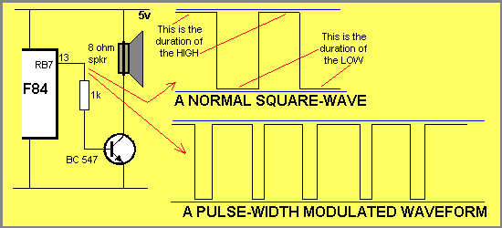
When
the HIGH is longer than the LOW, a completely different quality of the sound is produced
by the speaker.
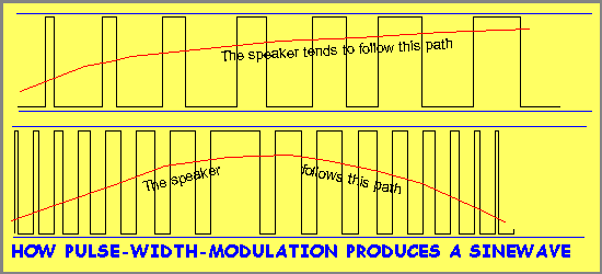
Depending on the length of the HIGH and LOW, different
qualities in the sound can be produced. When the HIGH is very short, compared to the LOW,
the cone of the speaker cannot respond to the rapid RISE AND FALLS, and moves along
an "average" path as shown above. This is how a smooth
sinewave can be produced from the speaker. The programming for this is very
complex and will be covered in a later exercise.
Go to the next page:
Programming Starts Here Page 2
 |


