|
Arc Welder Simulator |
For model railways . . .
by
Ken Stone
|
|
![]()
INTRODUCTION
Detailed workshops and maintenance yards can be the highlight of many
model railways or dioramas. Unfortunately they usually suffer from one
common problem. They are static. At the scale involved, it is not an easy
problem to overcome either. Moving parts at this size present quite a
challenge. 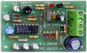
However making things move is not the only way to animate a scene. One classic sight in any industrial workshop or construction site is a man hunched over something he is welding, a fairly slow process that doesn't require much movement. None the less, anyone glancing in that direction is sure something is going on because of the flashes of light caused by the process.
Simulating such flickering is not difficult in electronics, and with
the advances in LED technology, can be quite convincing.
HOW IT WORKS
The arc welder simulator is made up from several functional blocks:
five oscillators, two gates and the output driver.
IC1A, IC1B and IC1C are all wired as square wave oscillators, each
operating at a different frequency under 100 Hz. The three outputs of
these oscillators are gated together by a NOR gate consisting of three
1N4148 diodes, a 100k resistor and IC1D. Only when the output of all three
oscillators are LOW, is a HIGH present at the output from IC1D. This
output is a pulse of semi-random duration and occurring at semi-random
intervals. This is used to generate the occasional bright flashes
associated with arc welding.
IC1E is also wired as an oscillator operating at a similar frequency to
the previous three, though unlike them, its pulse length is adjustable
from nearly 0 percent to 50 percent. This is used to generate the
consistent flicker. The adjustment is provided to give some control over
brightness, which is particularly important when using a lamp as the
output. If a fixed mark space ratio was used, some lamp filaments would
not achieve enough heat to glow during the short pulse.
The outputs of the NOR gate (IC1D) and the output of the flicker
oscillator (IC1E) are gated together by an OR gate consisting of two
diodes. This combines the flicker and flash, feeding them to the base of
the Darlington driver transistor via a 1k5 resistor.
An onboard LED is provided to allow monitoring of the output.
The circuit as described above would result in a never-ending welding
effect, and that would be as bad as not having any animation at all, so
the remaining Schmitt inverter IC1F was added to the circuit to switch the
effect on and off periodically. IC1F is wired as a square wave oscillator
with a cycle of several seconds. Its output is fed to the same OR gate as
the flash oscillators, and also to the flicker oscillator via 1N4148
diodes. When the output of IC1F is HIGH, the output of IC1D and IC1E are
both forced LOW, preventing any output, thus darkening any LED or lamp
connected to the output. When the output of IC1F is LOW the output of both
the flicker and flash sections are enabled, giving the welding effect.
While this cycle is predictable because of its square wave nature, the
period is long enough that is isn't that noticeable.
One other note about this oscillator: unlike the other oscillators in
this circuit, the timing capacitor is between the input of the Schmitt
inverter and the positive rail. This has been done so that when the unit
is first powered, the discharged 4u7 capacitor will hold the output of
IC1F LOW, allowing the effect to start immediately.
As the arc welder simulator is designed to be used with the
uncontrolled DC output of model railway transformers, a 1N4001 diode has
been used to provide polarity protection, and a simple zener/transistor
regulator has been included to limit the voltage to the chip to around 12
volts. Without this, the voltage of the model railway transformers could
push the power to the chip to over 15 volts, destroying it. The
uncontrolled DC output is usually rectified, but unsmoothed, and may be as
high as 15 to 18 volts, despite being labelled as 12v on the transformer.
CONSTRUCTION
| |
|
The arc welder simulator is built on a single sided PCB measuring about
5.5 cm by 4 cm. Before you start assembly, check the board for etching faults. Look for
any shorts between tracks, or open circuits due to over etching. Take this
opportunity to sand the edges of the board, removing any splinters or
rough edges. USE ADJUSTMENT Article, art & circuit design by Ken Stone.
When you are happy with the printed circuit board, construction can
proceed as normal, starting with the diodes and resistors first, followed
by the IC socket, then moving onto the taller components.
Take particular care with the orientation of the polarized components,
the diodes, LED, electrolytics and the transistor. The metal side of the
transistor is indicated on the PCB by and extra line on that side of the
component outline.
When inserting the IC in its socket, take care not to accidentally bend
any of the pins under the chip. Also, make sure the notch on the chip is
aligned with the notch marked on the PCB overlay.
The four external connections to the circuit are all at one end of the
board, via the terminal block. The two left most terminals, marked "-" and
"+" on the overlay are connected to the power supply. This can be a
regulated power supply providing 12V D.C., such as the Economy Power
Supply presented in Electronics for Model Railways book 2, or the
uncontrolled DC output of the model railway transformer. The kit for the
Economy Power Supply is also available from Talking Electronics.
The right most connections on the board, marked "+L" and "OP", are the
outputs for driving a LED or lamp respectively.
One of the relatively new high brightness 6000mcd white LEDs can be
used. These put out a bright bluish-white light quite reminiscent of the
output of an arc welder.
If you choose to use one of these LEDs, connect its anode (the long
lead) to the terminal marked "+L" and its cathode (short lead) to the
terminal marked "OP".
If you wish, a lamp may be connected here giving a reasonable effect.
The lamp should be rated around 3 watts, giving enough brightness for the
effect to work properly. The connections to the lamp are a little
different, and there may be issues with its voltage. The lamp should be
connected between the positive side of the power supply at the terminal
marked "+", and the terminal marked "OP". Ideally a 12 volt lamp can be
used, but depending on the actual output voltage of the uncontrolled DC
output of the model railway transformer, you may find yourself needing to
use a lamp that is rated as high as 18 volts. Be prepared to test the lamp
before building it into your layout. If you notice and silvering
occurring in the lamp after it has been running for a while, you will need
to find a lamp with a higher voltage rating. An alternative would be to
use several identical lower-voltage lamps in series. For example, three 6
volt lamps will give an overall rating of 18 volts.
By now you are probably wondering how a 5mm LED or 3 watt lamp are to
be hidden on the layout, as neither is particularly small. The trick is to
position them so that they throw light onto the scene around where the arc
welding it taking place, possibly under, or in front of the welding scene.
The source of the light (LED or lamp) should be hidden, for example in a
crate that has one side open, facing away from the viewing angle. Clever
use of reflective material can give the impression that an item is being
welded. Alternately, you may chose to hide the job being welded with the
body of the model welder, instead relying on the effect to show what is
happening.
When mounting the arc welder PCB, if you use metal spacers, make sure
they do not make contact with any of the PCB tracks, or short circuits may
result.
There is only one adjustment on the circuit board, that for the flicker
pulse width. Simply adjust it for the best effect. When driving a lamp
from the arc welder simulator, a portion of this adjustment will have no
visible effect as the pulse length is too short to heat the filament
enough for it to glow.
Kits for this project are available from
plus $4.50 postage.
![]()