More chapters of this eBook on:
Talking Electronics.com
For any enquiries email
Colin Mitchell
BASIC ELECTRONICS
(this is the Basic Electronics
section i.e. Page 1)
(Chapters 1 and 3 are available as .pdf )
Quick Quiz - to see how much you know
Encyclopedia of Components - this is excellent !!!
|
Page 1:
Basic
Electronics
(this page)
-
.pdf (1.2MB)
or .zip The capacitor - how it works The Diode - how the diode works Circuit Symbols - EVERY Circuit Symbol Soldering - videos Page 2: The Transistor - PNP or NPN Transistor TEST another TEST Page 2a: The 555 IC The 555 - 1 The 555 - 2 The 555 - 3 The 555 TEST Page 3: The Power Supply download as .pdf (900kB) 3a: - Constant Current 3b: - Voltage Regulator 3c: - Capacitor-fed Power Supply Page 4: Digital Electronics 4a: - Gates Touch Switch Gating 4b: - The DELAY CIRCUIT Page 5: Oscillators Page 6: Test - Basic Electronics (50 Questions) Page 7: The Multimeter - using the Multimeter Page 8: Constructing a Project Page 9: Inductance |
Remember:
the animations do not work in .pdf
the site is being constantly updated
You can get a lot more knowledge and understanding from our
pages of faulty circuits in
SPOT THE MISTAKE
P1
P2
P3
P4
P5
P6
P7
P8
P9
P10
P11
P12
P13
P14
P15
P16
P17
P18
P19
P20
P21
P22
P23
P24
P25
P26
P27
P28
P29
P30
P31
P32
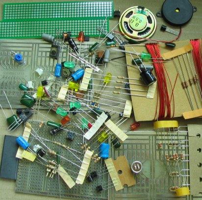
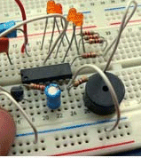
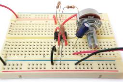
KIT OF PARTS
Talking Electronics supplies a kit of parts that can be used to build the majority of the circuits in this eBook.
The kit costs $15.00 plus postage.
Kit for
Transistor Circuits - $15.00 A
kit of components to make many of the circuits described in this
eBook is available for $15.00 plus $7.00 post. A
kit of components to make many of the circuits described in this
eBook is available for $15.00 plus $7.00 post.Or email Colin Mitchell: talking@tpg.com.au The kit contains the following components: (plus extra 30 resistors and 10 capacitors for experimenting), plus: 3 - 47R 5 - 220R 5 - 470R 5 - 1k 5 - 4k7 5 - 10k 2 - 33k 4- 100k 4 - 1M 1 - 10k mini pot 1 - 100k mini pot 2 - 10n 2 - 100n 5 - 10u electrolytics 5- 100u electrolytics 5 - 1N4148 signal diodes 6 - BC547 transistors - NPN - 100mA 2 - BC557 transistors - PNP - 100mA 1 - BC338 transistor - NPN - 800mA 3 - BD679 Darlington transistors - NPN - 4amp 5 - red LEDs 5 - green LEDs 5 - orange LEDs 2 - super-bright WHITE LEDs - 20,000mcd 1 - 3mm flashing LED 1 - mini 8R speaker 1 - mini piezo 1 - LDR (Light Dependent Resistor) 1 - electret microphone 1m - 0.25mm wire 1m - 0.5mm wire 1 - 10mH inductor 1 - push button 5 - tactile push buttons 1 - Experimenter Board (will take 8, 14 and 16 pin chips) 5 - mini Matrix Boards: 7 x 11 hole, 11 x 15 hole, 6 x 40 hole, surface-mount 6 x 40 hole board and others. Photo of kit of components. Each batch is slightly different:
|
|
BEFORE WE START Too many text books start with the physics of the atom and have equations and mathematics to show how smart the author is. Don't worry, we wont have any physics or equations. The reason . . . This is not a physics course. It is a practical electronics course to teach the basics as quickly as possible. There are no equations because most transistor circuits cannot be worked out mathematically as the gain of a transistor changes according to the current-flow and these gain-values are never provided. So the mathematics is worthless. To get an answer, all you have to do its build the circuit and measure the values with a multimeter. Also lots of discussions in text books will never be used in your next 40 years of electronics, so this course doesn't have any unnecessary material and is much-more concentrated than anything you have read before. Every frame contains important points - especially the animations - as they show you how a circuit works in slow-motion - something that has NEVER been done before. |
|
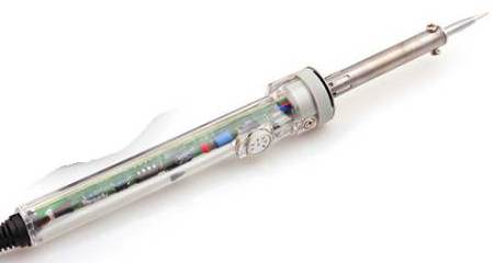
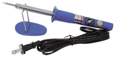
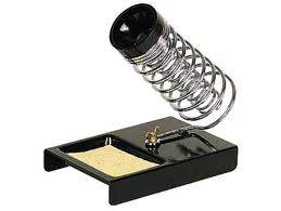
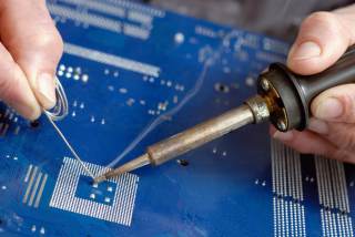
100 THINGS Here's a list of 100 things to get you started. Buy a soldering station for $50.00 with temperature control with a holder for the soldering iron. Buy 0.5mm resin cored solder Buy desoldering braid with the resin already added to the braid. Don't get the cheap stuff. Side cutters, screwdrivers and other tools $5.00 analogue multimeter and $8.00 digital meter from Aliexpress. and a $50.00 Digital CRO. DSO FNIRSI-138 2.4" TFT Digital Oscilloscope 1Msps + Analog Probe Bandwidth
AU $33.35 FREE
Shipping from mpsvadh Remember Store
It does not come with case but that does not matter as you
need to have access to the switches and buttons.
You need to make a stand so the screen sits back by 30
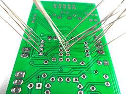
degrees and a 9v or 12v battery and switch.Once you get a number of projects working you will be shown how to use a CRO and it has a "run" and "freeze" setting so you stop the trace and count the cycles. Buy some cheap kits and look at Talking Electronics website for hundreds of transistor and 555 and digital circuits (linked below). Look at the kits of components from Talking electronics and the small breadboard. Make lots of circuits and get an idea of what each component looks like and change the values of the components to see what happens. Get the LED Tester kit and use it to test LEDs and read the value of voltage across each LED to see how the colour affects the voltage. Next you should sign up for one of the free PCB CAD packages and learn how to make your own Printed Circuit boards. Here is the Talking Electronics article on Matrix Boards and Prototyping Board and PCB CAD packages. You need to copy and make some simple boards from the time you start your course as this will be one of the most important parts of a successful career. Here is the list of 200 Transistor Circuits and IC Circuits and 555 Circuits Build the circuits and make sure they work and go to the next circuit. Get an idea of what a circuit looks like and be ready to draw a circuit FROM MEMORY. You have to get 300 circuits "under your belt" as an absolute preliminary to doing any sort of electronics course. Next you should read the article on THE TRANSISTOR AMPLIFIER and build the circuits so you know a little bit about how the transistor works BEFORE the instructor covers this in your course. It is pointless coming to a lecture, knowing nothing about what is to be taught. You can try this stupidity with engineering and medical courses but it does not work with electronics. Electronics needs a much deeper understanding than anything else because you cannot "see" what is going on with a circuit and you have to use your BRAIN to work out what is happening. That's why so few understand electronics. Next you should read the article on Testing Electronic Components so you have an understanding on what sort of problems you will come across in your career. |
|
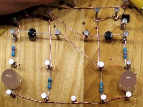
ELECTRONICS
BLOCKS Here is an idea from Instructables to produce blocks with screws, containing a single component and they can be connected with jumper leads (alligator clips). 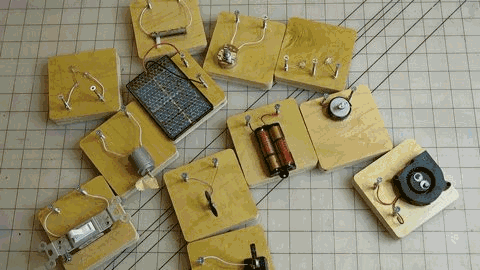 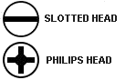 Use a slotted head for the negative screw and a philips head for the positive screw. |
Learn electronics from the beginning . . .
Milli -
milli means
1/1,000th (one thousandth) - such as one milliamp or one
millivolt.
START HERE:
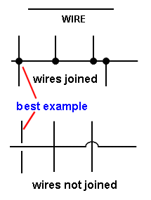
Fig 1 The wire in a circuit diagramAll electrical
and electronic components need wire to connect them to the
circuit.
In a diagram called a CIRCUIT DIAGRAM, the wires are drawn as
lines.
When the wires (or lines) cross, they may be joined or just
passing.
It is VERY IMPORTANT to show the difference between lines that
are JOINED and lines that are NOT JOINED.
When the lines are joined, it is best to place a dot on the
connection to PROVE the lines are joined.
When the lines are just crossing, a gap should be made so it is
obvious that one wire goes under the other and does not touch.
Lines should be "across the page" or "up and down." Very few
lines should be at 45°.
You can make a line thicker to indicate a power rail or a wire
that will be thick in reality.
![]() to
Index
to
Index
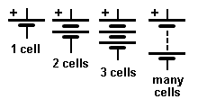
Fig 2 A single Cell and many
CellsNext we need a
battery.
A battery consists of two or more cells. The positive terminal
of a battery is the long line in the diagram and you must add
the voltage (of the cell or battery) to the symbol as a single
cells can be 1.2v, 1.5v, 2.2v or up to 3.6v.
The symbol does not let you know the voltage.
The positive is always at the top and is the longest line on the
battery symbol. ![]() to
Index
to
Index

Fig 3: A GlobeNext we need
a globe. A globe has two connections (a fine wire inside a
glass bulb glows when the globe is connected to a battery).
![]() to
Index
to
Index
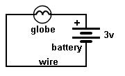
Fig 4: A CircuitWith a globe,
battery and wire we have produced a CIRCUIT.
A CIRCUIT is a complete path and we say the "electricity" the
CURRENT emerges from the positive of the battery, moves through
the globe and returns to the battery via the wire.
If the globe is a "3v GLOBE" it will glow when connected to a 3v
battery.
The globe can be connected either way around.
The circuit we have shown is called a SCHEMATIC and consists of
symbols: a globe symbol and a battery symbol.
The line connecting the two components is called WIRE. ![]() to
Index
to
Index
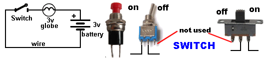
Fig 5:Adding a SWITCH
To turn the globe ON and OFF we need a
SWITCH.
The switch may be a push button, a toggle
switch (a "click" action)
or a slide switch. You could twist the wires together
and untwist them. The result is the same. We say the circuit is
"broken" or "open" via the switch and the lamp does not
glow. Closing the switch turns ON the globe.
![]() to
Index
to
Index

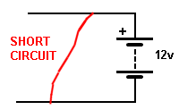
Fig 6: Naming the RAILSThe top rail of the CIRCUIT
DIAGRAM is called the SUPPLY RAIL or POWER RAIL.
The lower rail is called the 0v Rail or EARTH RAIL.
Do not connect the Supply rail (+12v) to the 0v rail as this
will cause a high current to flow and is called a SHORT
CIRCUIT:
![]() to
Index
to
Index
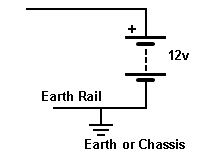
Fig 7: The EARTH RAILThe lower
rail is also called the Chassis.
This comes from the "old days" when electronics constructors
build radios on a metal chassis (metal box) and it was connected
via wire to a pipe in the ground to help
the radio pick up distant radio stations.
The term also comes from car and truck wiring where one
side of each globe is connected to the frame or chassis so that
only one wire is needed to each globe and the return "path" is
via the chassis. ![]() to
Index
to
Index
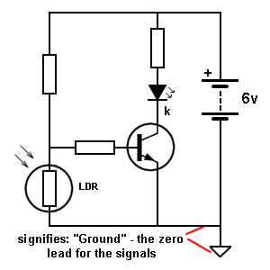
Fig 7a: GroundSome circuits identify the "Ground
Lead" or "Ground Wire" of a project to show where all
the signals have been "referenced to." In other words,
all the signals rise and fall above and below this "Ground wire"
or "Ground Lead." This lead may not be at earth potential
as the project may be in a plastic box but it identifies where
the earth lead of a Cathode Ray Oscilloscope or the negative
lead of a multimeter is connected.
On some printed circuit boards, the negative terminal of the
battery (the 0v wire or terminal) is connected to a very large
area of copper and this is called the EARTH PLANE or GROUND
PLANE. It is designed to prevent signals travelling along the
tracks (called traces) being radiated and also prevents outside
interference upsetting the project. It also "tightens-up" the
earth rail.
![]() to
Index
to
Index
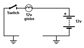
Fig 8: EARTH ReturnThe circuit
shows a 12v globe connected to a 12v battery and the circuit
appears to be "broken" (not continuous).
But the current returns via the
earth connection.
We talk about the CURRENT RETURNING. We don't say: the
voltage returning.
The voltage of the globe must be the same as the battery
voltage, otherwise it will not glow fully or it will
burn out
if it is say a 6v globe. ![]() to
Index
to
Index
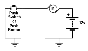
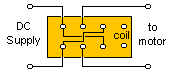
Fig 9: Connecting a MotorThe circuit shows a
12v Motor.
It is turned ON when the push-switch is pressed.
![]() to
Index
to
Index
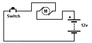
Fig 10: Reversing a Motor If the wires
are connected to the motor "around the other way," the motor
will reverse direction.
![]() to
Index
to
Index
VOLTAGE AND CURRENT
What is voltage and what is current?
Here is a very simple description.
A battery produces a voltage called DC. (This is a very
confusing name because the letter actually refer to Direct
Current, so we just say DC Voltage).
A battery also produces current called DC - Direct Current. We
say DC current.
VOLTAGE
Voltage is a value produced by an electrical component called a
battery or cell.
A single cell produces one and a half volts. (1.5v) and although
this is not a high voltage, when cells are connected together we
get higher voltages.
If 6 cells are connected in series we get 9v.
Here is a 9v battery:
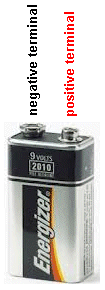
Touch the two terminals with your tongue. You get a tingle. This
is a 9v tingle. Now you have "felt" electricity. This is a 9v
tingle.
CURRENT
You cannot feel current
with your tongue so we have to carry out another experiment:
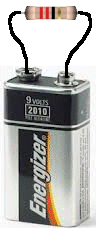
Place a 22 ohm or 47 ohm resistor across the terminals of the battery and
hold your fingers on the resistor. It will get hot. This is the
result of current flowing through the resistor and heating it
up. The current will be about half an amp and the voltage is 9v,
so the wattage will be about 2 to 4 watts.
Feel the heat produced.
In other words one thousand milliamps is equal to 1 amp.
One volts is not a very large value as a battery produces 9v and
a cell produces 1.5v to 3.6v (depending on the type of cell.
But 1 amp is a large quality when talking about electronic
circuits involving LEDs, motors and transistors.
The globe used in the experiments above requires about 300mA.
(1,000mA = 1 amp)
The 3v motor used in the experiments requires about 250mA
The LEDs used in the experiments require about 20mA.
Transistors can pass about 100mA to 800mA via the
collector-emitter.
In most cases current-flow in the circuits we will be discussing
will be less than 1 amp and will be shown as 25mA, 100mA, 350mA
etc.
WATTAGE and CAPACITY
A 9v battery has 6 very
small cells and they will not last very long.
A "AAA" cell is larger and a "D" cell is much larger.
 A large cell is said to have a
LARGE CAPACITY.
This means it will deliver a larger current for a
longer period of time.
A large cell is said to have a
LARGE CAPACITY.
This means it will deliver a larger current for a
longer period of time.
The WATTAGE of a cell is the multiplication of the voltage x
current. The answer is milliwatts or watts.
This is like asking a "muscle man" how much weight he can lift.
It is an INSTANTANEOUS value. But the "muscle man" may be
only able to lift weights for 10 minutes whereas another man may
be able to lift the same weights for 30 minutes. The second man
has more CAPACITY.
The CAPACITY of a cell is the wattage x hours. The answer is
milliwatt-hours or watt-hours. This is also called watt-hours.
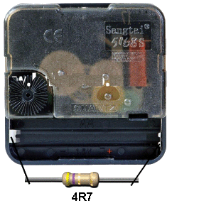
You can determine the capacity of a cell (such as a rechargeable
cell) by connecting it to a clock-mechanism that has a 4R7
connected across the terminals. The resistor will take a
considerable current and deplete the cell in a few hours. The
clock will let you know exactly how long the cell delivered the
current. You can then compare other cells.
QUESTION: What is the component in a cell that decides
the capacity of the cell?
Sometimes you can buy AA cells that last 6 months in a door bell
and other last 12 months.
Obviously one cell has twice the CAPACITY. But what decides
this?
Basically it is the zinc casing. The zinc casing gets eaten away
as it delivers energy to your circuit. Or it can be the amount
of Manganese Dioxide in the middle of the cell. This is mixed
with Carbon to reduce the resistance of the mixture. But Carbon
is cheaper and when the Manganese Dioxide gets used when the
cell delivers a current, it becomes very high resistance and the
current drops. There is one more chemical in a "dry cell.
It is Ammonium Chloride and blotting paper is soaked in this
solution and placed against the zinc case. The cell is not dry
as current would not flow if it is dry. But when you deliver a
current the cell makes extra "water" and the chemicals in the
cell absorb the water and produce a new chemical. If the zinc
case is eaten away and a "pinhole" is produced, a solution of
chemicals will flow out the hole and the cell is said to the
"leaking." This happens when the chemicals inside the cell
cannot convert the "water" into a new chemical that does not
"leak."
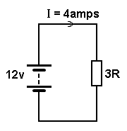
The simplest electrical circuit consists of a battery and
resistor.
The current flowing through the
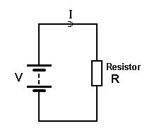 circuit
will depend on the voltage of the battery and the resistance of
the resistor R.
circuit
will depend on the voltage of the battery and the resistance of
the resistor R.
The formula connecting these three quantities is:
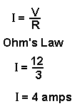
This is called
Ohm's Law.
Suppose you have a 12v battery and the resistor is 3 ohms. The
current flowing through the resistor will be 4 amps.
Increasing the resistance will decrease the current if the
voltage remains fixed.
All the above circuits are called ELECTRICAL
CIRCUITS because they contain electrical components (such as
a motor, globe, relay, switch).
When the circuit contains an ELECTRONIC component such as
a diode, transistor, LED, it is called an ELECTRONIC CIRCUIT or
ELECTRONIC SCHEMATIC.
![]() to
Index
to
Index
POWER and ENERGY
Here's an easy way to
remember the difference between POWER and ENERGY:
A 9v alkaline battery has enough ENERGY to start a car. But it
does not have enough POWER (strength).
Energy is effectively the strength of the battery (and this is
the voltage and the current it can deliver) multiplied by the
time it can deliver this energy. When the answer is obtained, it
consists of three factors ((3 quantities) VOLTS, AMPS and TIME.
This results in an answer called xxxx WATT-HOURS.
For a 9v battery the quantities are: 9 volts, 500mA and the
battery will deliver this 9x0.5 = 4.5watts for about 1 hour.
This is equal to 4.5 x 60 x 60 = 16,200 watt-seconds.
To start a car requires 250 amps from a 12v battery for 5
seconds.
This is: 12 x 250 x 5 = 15,000 watt-seconds.
This means the energy stored in a 9v battery could start a car
if all the energy could be delivered in 5 seconds.
This is not possible however the FACT is this: A 9v battery has
enough stored energy to START A CAR. ![]() to
Index
to
Index
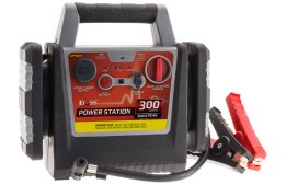 |
BATTERY
BOOSTER One of the simplest things we can do is start a car with a flat battery with the assistance of a BATTERY BOOSTER. This consists of a 12v rechargeable battery in a handy case with leads to connect to the flat battery in your car. This simple operation puts two 12v batteries in parallel, but no-one has actually described what happens and why. That's because the explanation is very complex. We have included it here to show that a simple explanation involves a lot of technical terms and you will understand more after reading the course. |
|
The flat battery in the car is not fully charged
but it has some percentage of charge and when it sits for a
period of time in a non-fully charged condition, the voltage
drops from 12.6v to less than 12v as the battery gradually
self-discharges due to the potential at the top of the cell
being different to that at the bottom of the cell and the
specific gravity of the electrolyte being different at the top
and bottom. This causes an internal current to flow within the
cell and slowly discharge the cell. But if you try
to start the car, the voltage drops to less than 7v because the
electrolyte cannot carry the high current and a slight potential
is developed across the liquid. The result is the
starter-motor does not crank the car. The reason is this: When the battery is fully charged, the current taken by the starter motor is about 300 amps. This is about 11v x 300 amps = 3300 watts = 4.4Horsepower. But when the voltage drops to 7v, the current will drop to 190 amps to deliver 1336 watts = 1.8HP. This is only 40% of normal and that's why the car does not start. The engine needs 4HP to overcome the pressure in the cylinders due to the compression of the air during the "firing stroke." Let's put it this way. If we have a brand new 7v battery, the car will not start. The starter-motor will only accept 190 amps when the supply is 7v. So, we have to increase the voltage. We do this by placing a 12v battery across the flat battery. The voltage of the flat battery will immediately rise to 12.6v. It might take 2 minutes but the flat battery will take a small current (1 to 10amps) from the battery in the "booster" and the output of the combination will be 12.6v. The current-carrying capacity of the electrolyte will improve very quickly and you have effectively given the "flat battery" a very quick charge. The starter-motor will now accept 300 amps from the combination and SURPRISINGLY the cells of the "flat battery" will deliver about 200 amps and the booster battery will deliver about 100 amps. The actual sharing of current will depend on the two batteries but the secret behind the success is the increase in voltage we call TERMINAL VOLTAGE. The voltage on the terminals (the alligator clips). The capacity of the booster battery is not important. It can be from 7AHr to 40AHr. We are just using a very small amount of its capacity to start the car and nearly all batteries will provide 200 Amps for a short period of time. The voltage of the car battery is very important. The Horsepower taken by the starter-motor is defined by the formula: Pwatts = V2/R Since the resistance remains constant, a voltage of 7 volts will produce 7x7=49 units and a voltage of 11v will produce 121units. This gives the ratio of 40% to 100% as explained above. |
|
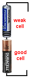
|
BATTERY BOOST Continuing from the previous frame where we showed the effect of placing a weak battery in parallel with a good battery, we can show what happens when a weak cell is placed IN SERIES with a good cell. This also applies when you have 5 good cells and one weak cell. Basically, the weak cell will reduce the current. In other words, if the 5 cells are driving a motor and supplying 250mA, the 5 cells and 1 weak cell will deliver 200mA or less, depending if it is weak or very weak. The current flowing through the weak cell will have the effect of giving it a small charge - in other words, you will be charging the weak cell from the good cells when the motor is operating. BUT . . . . There is a way to use weak cells. If you have say 6 weak cells driving a motor and the RPM is reducing, you can add 2 more weak cells to increase the RPM. The effect is this: The voltage from the 8 cells will be higher than from 6 cells and this will allow a higher current to flow. Sometimes the cells will provide this higher current and thus more of the energy will be delivered and you will get the last of the energy from the cells. |
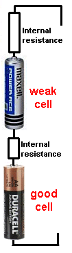 |
INTERNAL
RESISTANCE All batteries and also all individual cells have a "secret, hidden" value of resistance inside each cell due to the resistance of the chemicals. This resistance is very small when the cell is new but it increases as the cell gets older. It is very easy to measure this value. Simply put an ammeter directly across the cell and measure the current. Use Ohm's law to work out the resistance. But this not always a wise thing to do as some cells will deliver 10 amps and some will deliver 100 amps and damage the meter. The diagram opposite shows a large internal resistance for the weak cell and a small internal resistance for the good cell. If a cell did not have any INTERNAL RESISTANCE it would deliver thousands of amps. It's the Internal Resistance that limits the current. In most cases we neglect (do not consider) the value of internal resistance when making tests and when using a battery in a project. But when a battery gets old, it cannot deliver a high current and the internal resistance gets so high that the output voltage drops from say 9v to 7v, even when the battery is not connected to a circuit. This is the result of the INTERNAL RESISTANCE of the chemicals increasing to a point where they become noticeable and what we call "poisoning" of the chemicals due to the cell "aging" and new chemicals being produced in the cell that have a high resistance. Some of the terms we use are: "drying out and sulphating. Some cells produce spikes or needles that completely short-circuit the cell and make it totally useless. |
 This resistor is dissipating 48 watts. As a comparison, a soldering iron is dissipating about 10 to 20 watts. |
RESISTOR
WATTAGE Resistor Wattage means two things. 1. The physical size of a resistor tells you number of watts it is capable of dissipating. This is called RESISTOR WATTAGE. It is really RESISTOR-SIZE or RESISTOR-CAPABILITY. 2. The multiplication of the voltage across a resistor and the current flowing though it will produce a value called WATTAGE. This is also called RESISTOR-WATTAGE or RESISTOR-LOSS or RESISTOR-DISSIPATION or HEAT-LOSS. In the circuit shown, the wattage being lost in the resistor is: 12 x 4 = 48 watts. Most of the resistors we will be using in our projects are 0.25watts. This means they will dissipate 250milliwatts, however the actual wattage being dissipated may be only 70 milliwatts and the resistor will not get hot. 0.25watts is the maximum wattage it can dissipate without overheating. If it is dissipating 400milliwatts, it will be VERY HOT. The wattage it is dissipating (the heat it is getting rid of) will depend on the supply voltage and the value of the surrounding components. |
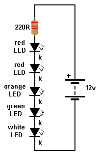
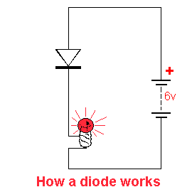
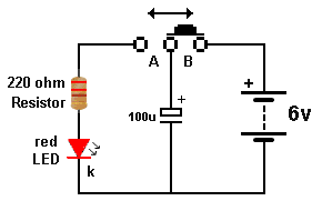
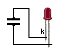
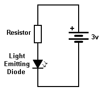 Fig 11. The LED |
This simple ELECTRONIC
CIRCUIT contains a LIGHT EMITTING DIODE (LED),
RESISTOR and battery. The circuit is classified as electronic because the LED is not an electrical item (such as a globe) but more-complex, as it produces light when current flows through a crystal and the crystal produces the colour. |
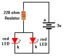
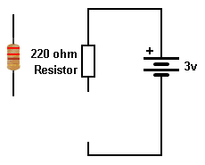 Fig 12. The Resistor |
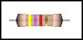
A RESISTOR must be
included in the circuit to prevent the LED being damaged. The resistor in this circuit must be 220 ohms. This is shown by the colours on the resistor. The colours for 220 ohms: red - red - brown. The 4th band is gold - indicating a tolerance of 5%. A resistor has RESISTANCE. It reduces the current from the battery to a required amount to prevent the LED glowing too bright. A resistor is just like putting your foot on a hose. The water trickles out the end. The resistor "resists" the high current-flow that the battery is able to deliver. |
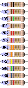
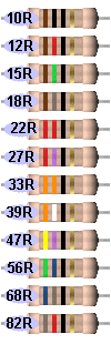
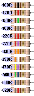
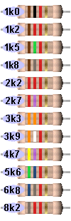
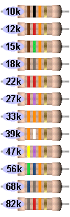
 Fig 12a. The Resistor Colours |
There are
hundreds of different resistors because the resistance-values
need to cover the range one ohm to 10 million ohms. There are also small, medium and large resistors. The resistors on the left are just a few in the range. (See the full range below). They show colour bands for 1 ohm to 8.2 ohms and 1 million ohms to 8.2 million ohms. All the other values are shown below. An electronics engineer does not have the room to store 10 million different resistors so they make each resistor 5% or 10% higher than the previous. This reduces the number to about 100 to 200. TOLERANCE The first 3 bands indicate the value of the resistor and the 4th band indicates either 5% or 10% tolerance. All modern resistors are 5% or 2% or 1%. The "old" 10% resistors are no longer made. Gold = 5% Silver = 10% |
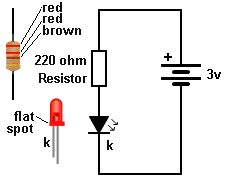 Fig 13. The Resistor and LED |
The LIGHT EMITTING DIODE
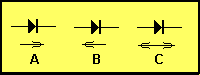
is called an electronic component (mainly because it is more
complex than a globe and it produces light by a more-complex
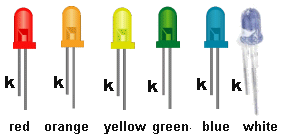
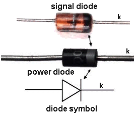
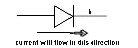
means than heating a wire). A LED must be connected around the correct way. It will not illuminate if connected around the wrong way. All LEDs have one lead longer than the other. The SHORT lead is called the CATHODE (k). All LEDs have a flat on one side and this is the CATHODE lead. The arrows on the diagram indicate light is "given off" (emitted - produced). |
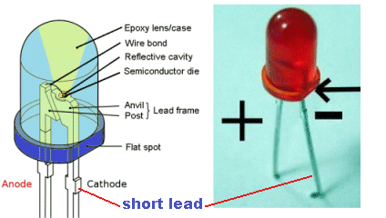 Fig 14. The LED - showing the flat spot A close-up of a red LED. The cathode lead is the short lead and next to a flat side on the LED. DO NOT show "+" or "-" on a diagram. Only show the letter "k" to indicate cathode. The symbols "+" and "-" are used when a component produces a voltage or is connected directly to "+" and "-" A LED is connected via a resistor. |
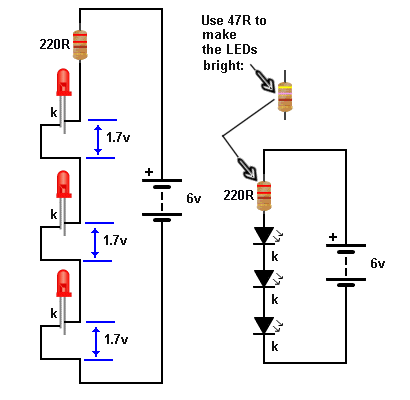
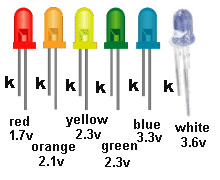 Fig 15. LED VOLTAGES |
When a LED is
connected to a circuit, (and the correct-value resistor is
included), a voltage will be develop across the LED called the
CHARACTERISTIC VOLTAGE DROP. This voltage is due to the colour of the LED and the crystal inside the LED that produces the colour. The diagram on the left shows the approximate voltage developed for each LED. The voltage does not change for small, medium, surface-mount, or large LEDs. |
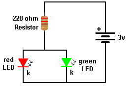
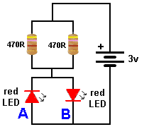
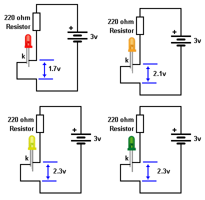 Fig 16. LED VOLTAGES |
When a LED is connected to 3v
battery, the following
CHARACTERISTIC VOLTAGE DROPs will develop across each LED.
You will notice we have not changed the value of the resistor. It is 220R. The LED creates the voltage and if the value of resistance is decreased, the LED will illuminate BRIGHTER. If the LED illuminates too bright it will be DAMAGED. |
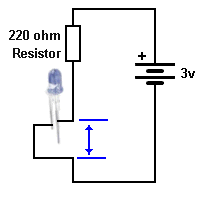 Fig 16A. The RESISTOR |
Question from a
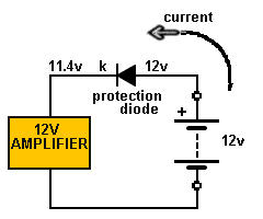
reader: "Is the current lower after a resistor?" The answer is YES. But that is NOT the way you "see" how the resistor works and NOT the way to analyse a circuit. When a resistor is added to a circuit, the current will reduce and this current will be the same "entering the resistor" as "leaving it." Here's how the circuit works: When a resistor is added, the current through the circuit will reduce and the amount of current (value of current) through the resistor will produce a voltage across it. This voltage is subtracted from the supply voltage and now we have a lower voltage-supply. |
| This new value of voltage will
cause a lower current to flow through the circuit. The "thing" that causes current to flow through a circuit is VOLTAGE. The amount of current depends on the resistance of all the components in the circuit. More from a reader: "Is the voltage higher before a resistor?" YES. When a resistor is placed in a circuit and the circuit is "operating" a current will be flowing. The voltage on one end of the resistor will be higher than the other end. This proves a current is flowing. Sometimes this is the easiest way to detect a current in a circuit. You don't have to cut or remove anything. By measuring the voltage across the resistor and knowing the value of resistance, you can determine the current flowing. That's what this course is all about. |
|
|
Fig 17. WHITE LED VOLTAGE |
If we connect
a WHITE LED to 3v supply, it will not illuminate because it
needs a supply higher than 3.6v. The resistor in series with the LED is called a CURRENT LIMITING RESISTOR. In this circuit no current flows because the supply is not high enough. |
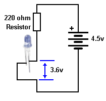 Fig 18. WHITE LED VOLTAGE |
When the
supply is increased to 4.5v, the 220R resistor will allow a
current to flow through the white LED and it will develop a
CHARACTERISTIC VOLTAGE DROP of 3.6v across it. The supply (the voltage of the battery) must be higher than the CHARACTERISTIC VOLTAGE DROP of the LED so the resistor will allow the correct amount of current to flow. The ideal current for a LED is 20mA, however some LEDs will work when 1mA flows, so you have to know what you are doing. |
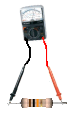
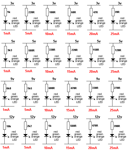
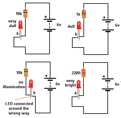 Fig 19. Testing A LED Now connect either the 1k, 470R or 220R and determine the brightness you need. As the brightness increases, the current will be higher. You can use 3v supply for all LEDs except blue and white. HOW TO TEST A LED Some clear LEDs produce red or orange and some LEDs do not have the cathode lead clearly identified. Here's how to find the colour, cathode lead and the current. You need a 6v battery, 10k resistor, 1k resistor, 470R resistor and 220R resistor. Connect the 6v battery and 10k resistor to the LED and it will only illuminate when the cathode is connected to the negative of the battery. This is the short lead. |
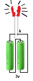 Fig 20. Damage a LED |
Do not connect a 3v battery directly across a LED. It will be DAMAGED. You MUST include a resistor. |
| A
LED IS CURRENT DRIVEN
You may have seen this statement and tried to work out what it means. Basically it means an increase in current will make the LED brighter. But a LED needs 2 things: It needs a voltage that is EXACTLY the voltage required to produce illumination. And this voltage depends on the colour of the LED. As soon as you supply the exact voltage, the crystal will begin to glow and as you increase the current, the illumination will increase. But doing this is VERY VERY difficult. It is very easy to supply an exact voltage such as 1.7v or 3.4v, but delivering a current such as 10mA or 20mA at the same time is very difficult. You cannot get a 1.7v battery and deliver 10mA to a LED. As we have shown above, you need a simple components such as a resistor between the battery and LED to achieve the desired result. A LED is CURRENT DRIVEN but firstly you need to provide a VOLTAGE that is exactly the connect value for the colour of the LED and then the current can be increased. |
 |
 |
 |
 |
 |
 |
 |
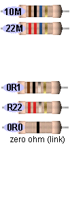 |
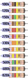
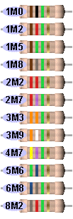
Here are all the colours and values for the resistors you will using in this course. Just match-up the colours on your resistor with the resistors above and you will find the value.

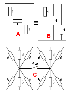
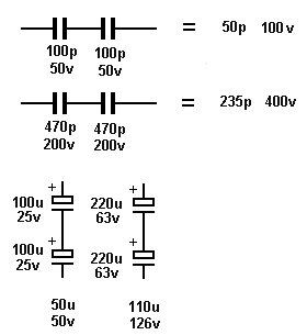
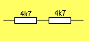
 The
two left resistors create 4 ohms and the two right resistors
create 4 ohms.
The
two left resistors create 4 ohms and the two right resistors
create 4 ohms. 


 The
capacitor can perform many different functions and produce many
different effects, depending on its value and the surrounding
components.
The
capacitor can perform many different functions and produce many
different effects, depending on its value and the surrounding
components. 
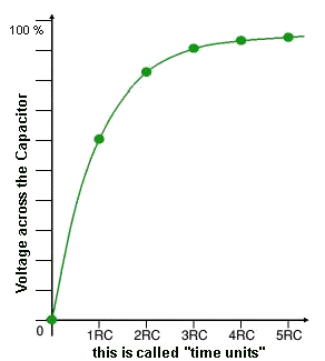
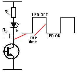
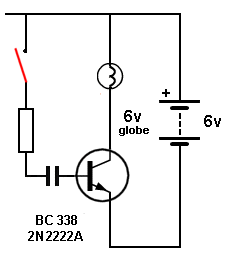 The animation shows a capacitor charging (via a resistor).
The initial current is LARGE and this turns the transistor FULLY
ON and the globe illuminates. As the capacitor charges, the
base current reduces and the transistor starts to turn OFF.
Eventually the capacitor is fully charged and the voltage on the
base falls to 0v, turning the transistor OFF.
The animation shows a capacitor charging (via a resistor).
The initial current is LARGE and this turns the transistor FULLY
ON and the globe illuminates. As the capacitor charges, the
base current reduces and the transistor starts to turn OFF.
Eventually the capacitor is fully charged and the voltage on the
base falls to 0v, turning the transistor OFF.


 The
Collector
The
Collector NPN Transistor
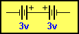 3v
3v 4k7
4k7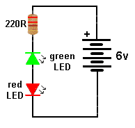
 10k
10k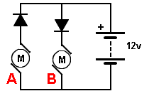

 A
A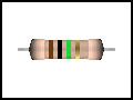 100k
100k