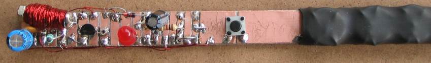
The completed Zener Diode
Tester showing the placement of the components
Do not fit the LED when testing a zener diode. The LED reduces the output of
the high-voltage section.
Two wires have been included across the zener for connecting a digital
multimeter.
THE
CIRCUIT
The circuit is a single building block called a flyback oscillator. This type
of oscillator energises an inductor then turns off very quickly and the
magnetic field produced by the inductor collapses and produces a very
high voltage in the opposite direction.
A diode on the output of the inductor passes this high-voltage-spike to
a 1u electrolytic, which stores the energy and provides a high voltage output.
The voltage produced by the inductor is over 120v but the transistor
will zener at a voltage lower than this and thus the output voltage will
be determined by the characteristic of the transistor.
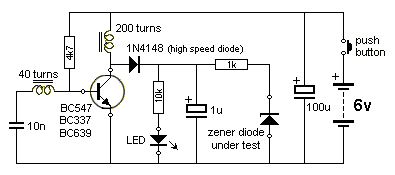
Zener Diode Tester Circuit
HOW THE
CIRCUIT WORKS
The heart of the design is a simple transformer.
It has a primary winding of 200 turns and a feedback winding of 40
turns.
We use the primary winding as a secondary and "tap-off'" the voltage
when the magnetic field is collapsing.
The interesting part of the transformer is this:
It is hand-wound on a bolt - called a "metal thread." Simply fit a
nut to the end of the end of a 3mm dia bolt with approx 16mm of thread and you have a handy core for the transformer. Use a steel bolt and
it will be just as good as a ferrite core for this application.
By winding the transformer yourself, you will learn a lot about transformers.
Firstly it does not matter if you wind the turns in layers or
jumble-wind the wire.
Also it does not matter if you wind the primary or feedback winding
first. The gauge of the wire is not important however we used 0.25mm
wire as this fills the core and makes a neat job.
It does not matter which way you wind the turns as the circuit will have
to be checked when it is turned on. If the LED does not illuminate, you
must reverse the feedback winding. Or you can reverse the primary
winding. BUT NOT BOTH. The feedback winding must produce a voltage in a
certain direction when the circuit is operating and this can be
determined by simply connecting the circuit and reversing the feedback
winding if it does not work.
When the circuit is turned on, the 4k7 delivers a current to the base of
the transistor and this turns it on a small amount and current flows
through the collector-emitter of the transistor and through the 200
turns of the transformer.
This produces expanding magnetic flux and this flux cuts the turns of
the feedback winding and produces a voltage in the turns that ADDS to
the voltage and CURRENT provided by the 4k7 to turn the transistor on
HARDER.
The voltage produced by the feedback winding comes out both ends of the
winding but on the left-hand end is a capacitor and when you try to
charge a capacitor quickly, it has a "resistive force" a bit like trying
to close a shock-absorber quickly.
This means only a small amount of energy flows out the capacitor end of
the feedback winding and most of it flows into the base of the
transistor.
The transistor turns on more and more and more until finally it is
turned on as hard as possible. At this point, the current through the
200 turns of the transformer is a maximum but suddenly the magnetic flux
is not expanding. It is steady or stationary flux.
This type of flux cuts the turns of the feedback winding but does not
produce a voltage in the winding.
This means the voltage and current produced by the feedback winding
suddenly stops.
This instantly turns off the transistor a fair amount as it only being
delivered the energy from the 4k7.
The current though the 200 turns suddenly stops and the magnetic flux
stored in the bolt is released but this flux is called collapsing flux
and causes voltage to be produced in both windings of the transformer IN
THE OPPOSITE DIRECTION.
This is the amazing part of a transformer.
The second amazing fact is this:
Because the collapsing flux is collapsing at a very fast rate, it
produces a very high reverse voltage. This voltage can be 10, 50, 100,
or even 1,000 times higher than the supplying voltage and the ratio of
the supplying voltage to the produced voltage is called the "Q" of the
transformer. The letter "Q" stands for the "Quality" of the transformer
(of the circuit).
In our case the supplying voltage is only a few volts but the produced
voltage is about 45v for a BC547, 65v for a BC338 and about 100v for a
BC639.
These voltages depend on two things:
1. The "power" of the transistor. The current capability of the
transistor. The ability of the transistor to pass a current though the
200 turns.
2. The natural zener characteristic of the transistor. Every transistor
has a maximum voltage that can be applied across the collector-emitter
terminals (and all the other terminals) before it will break-down (or
zener).
These two characteristics come into play with this circuit and that's
why the different voltages are produced any why each transistor takes a
different current from the battery.
The current can range from 40mA to 120mA.
That's why we have added a 100u electrolytic across the battery.
MAKING A TEST
The circuit will test NPN transistors, LEDs and zener diodes.
Three sets of pins have been provided for this purpose.
TESTING A TRANSISTOR
When testing a transistor, fit it into the pins marked C B E. If you
have a LED connected to the LED terminals, it will glow.
If you remove the LED and measure the voltage across the 1u
electrolytic, it will provide the maximum working voltage for the
transistor.
TESTING A
LED
When testing a LED, fit it into the pins for the LED with the cathode
lead (the shorter lead) to the left. It will glow very dim because the
dropper resistor is very high and only allows 4 - 6mA to flow.
This will give you a good idea of the relative brightness of a LED when
compared to others in a batch.
TESTING A
ZENER
When testing a zener, place it in the pins provided. If the zener is
around the wrong way, the voltage across it will be less than 1v.
When it is placed correctly,
you can read the zener voltage with a high impedance multimeter such as
a digital meter.
|
|
|
1
- 1k
1 - 4k7
1 - 10k
1 - 1u 63v electrolytic
1 - 100u 16v electrolytic
1 - 1N4148 diode
3 - zener diodes (various voltages)
1- BC 547 or BC338 or BC639 transistor
1 - 5mm red LED
1 - tactile push-button
1 - 16mm x 3mm bolt with nut
4m - 0.25mm enamelled wire
1 - 20cm fine enamelled wire
1 - 50cm fine tinned copper wire
7 - machine pins
7cm heatshrink tubing
5 - button cells
AG12, AG13, 357 or 386
1 - Zener Tester blank PC BOARD
1cm x 18cm
|
|
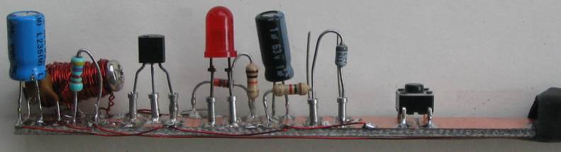
ASSEMBLY
The advantage of this project is you can make it from your "Parts Box."
No PC board is needed. All the parts are mounted on a strip of single or
double-sided copper clad board.
Double-sided is best as it allows fitting the button cells with wires
that hold them in place and make connection to the positive terminals.
These wires are then taken to the underside of the board and joined to
the next cell with links.
But if you don't have all the parts, it is best to get a kit as you will
need to buy the parts for many different suppliers.
Begin construction by cutting the board at 3-4mm intervals with a saw, file or
knife. Make sure the cuts separate the lands completely and do produce
any short-circuits.
Some of the lands are wider than the others, so look at the construction
diagram carefully.
Make the transformer by winding 200 turns onto the bolt and end the
winding at the same end of the bolt. Twist the two wires together.
Wind 40 turn on the other and twist the end together.
Now cut the wires very short and tin the ends by removing the enamel
with a sharp knife or hot soldering iron.
The transformer is now ready for fitting.
Start at one end of the board and fit each component as you come to it.
When fitting the machine pins, hold them by fitting a resistor lead into
the hole.
The transistor will not be fitted to the board. 3 machine pins allow
different transistors to be tested in the project.
The LED and zener diode is also not fitted. Machine pins allow these
devices to be fitted "under test." You can only test a LED or
zener but not both at the same time.
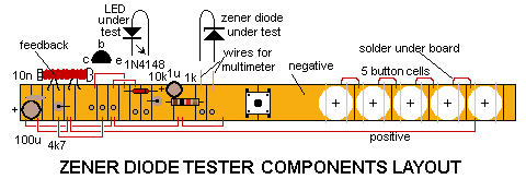
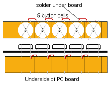
FITTING THE BUTTON CELLS
The 5 button cells are fitted to the board with fine tinned copper wire.
The underside of the board is used as the positive terminal of each cell
and this is connected to the negative of the next cell with short length
of wire.
Make sure the edge of the top layer of copper is removed from the two
sides of the PC board so that is does not "short-circuit" with the wires
going to the underside of the board.
Two fine tinned copper wires form a cross and are soldered over each
button cell when it is placed with the positive terminal UP on the
board.
Refer to the following diagram for connection of the cells.
Make sure the cells make contact by checking the supply voltage before
fitting and shrinking the heat-shrink tubing.
Finally fit a transistor and LED to the board and the project is
ready for testing.
TESTING
When the power is applied, the LEDs will illuminate
fairly dimly. This will indicate the high voltage is being produced.
If the LED does not illuminate, swap the connections of the feedback
winding.
Check the current consumption. It will be about 40mA for a BC547 and up
to 120mA for a BC639.
If is more than 200mA, a fault exists. If the 10n is not connected, the
circuit will take a high current and fail to work.
You can try connecting the 4k7 to the join of the 10n and feedback winding.
This will cause the circuit to take more current but the output voltage will be slightly higher.
Check for shorts between adjacent lands.
If no current is being taken by the circuit, either the cells are not making
contact or the 4k7 is not turning the transistor on.
Make sure the high-speed diode is 1N4148 and not a zener diode as a zener
diode will "break down" and only allow the zener voltage to appear on the
output.
Do not load the output when making the first test. You can leave the output
open and the voltage will rise to more than 45v.
Try different transistors and you will find the output voltage will change
according to the characteristics of the transistor.
A push-button has been used so that the circuit cannot be left on. Make sure
you have soldered it correctly and the circuit turns off when not being
pressed.
This covers all the possibilities and the circuit will be working for you.
Try the three zeners in the kit and determine their voltage.
You can get lots of unknown zeners from old computer boards.
And you can try different transistors to see their maximum voltage-rating.
MORE TO COME
This project will be updated and we will add links
to other Talking Electronics projects, as this series of projects is
delivered in the pages of Electronics Maker.
You will find this project very handy for testing transistors, LEDs
and especially unknown zeners as a high voltage supply is difficult to
find, for testing zeners.
COMMENTS
Add your comment to the article by emailing
Colin Mitchell.
24/5/2013 |