|
Capacitor Discharge Unit |
The name: Capacitor Discharge Unit with SPDT Switch - SLIM
has been chosen to identify it from all the other CDU modules made
by Talking Electronics. We do
not used code numbers such as ZL-36-A as they mean NOTHING, so a
full name is used.
Talking Electronics has produced a number of
It combines a number of features with a clever circuit to allow a single 1,000u to be charged to 35v and produce sufficient energy to operate a point. It also has an on-board mini toggle switch and two indicator LEDs - this reduces your wiring.
The first electrolytic on the PC board is called a RESERVOIR CAPACITOR as it does not play any part in the delivery of the energy to the point, but it sits between the positive and 0v rail to reduce the impedance of these two rails.
When the toggle switch is in the UP position, the other electrolytic gets charged and it puts a heavy load on the supply when this is happening.
This is when the peak current is drawn at the beginning of the charging cycle and rather than taking a lot of current from the supply, it draws much of the energy from the RESERVOIR CAPACITOR - about 80% to 90%. This energy is taken from the Reservoir Capacitor during the initial part of the cycle and the power supply assists during this time as well as the remainder of the time when the DELIVERY CAPACITOR is charging to its final value. This results in a very short charge-time.
When the switch is in the DOWN position, all the energy in the DELIVERY ELECTROLYTIC is passed to the point and the rest of the circuit is not involved.
Normally, the DELIVERY ELECTROLYTICS take a period of time to recharge, but with this circuit the Reservoir capacitor contains a lot of the recharge energy and the supply only has to supply a small additional amount during the activation and the remaining amount can be delivered after the point has changed position.
This means the point can be changed from one position to the other repeatedly, in less than a second.
The circuit also includes a voltage doubling arrangement for 12vAC to 15v AC - (from a train power supply) and two indicator LEDs to show the position of the point.
The mini toggle switch can be easily fitted to your console and small holes on each side of the switch used for the LEDs to shine through the console.
All these features are in this narrow PC board so that a row of these modules can be aligned on a panel to show the position of the points.
This module reduces your wiring considerably as only 3 wires are needed for each point and a common "bus" of positive and negative to the modules.
THE CIRCUIT

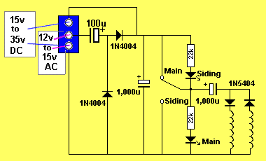
The circuit for the CDU point
controller
The circuit looks simple but the action of
the toggle switch produces two different paths for the DELIVERY
ELECTROLYTIC and the two power diodes connected to the ends of the
solenoid determine which coil will be activated.
The voltage-doubler, made up of a 100u electrolytic and two power diodes
is very effective in charging the 1,000u Reservoir Capacitor very
quickly to make the "recovery time" very short.
12v AC can have a peak as high as 18v and the voltage doubler will
increase this to nearly 36v (less a volt drop across the diode).
The voltage across the Reservoir Capacitor only drops about 10v during
an activation and it quickly recovers. It is only used every
alternate activation.
1,000u at 35v provides twice the energy as a 1,000u at 25v. That's
why this module is equal to our previous module using 2 x 1,000u @ 25v.
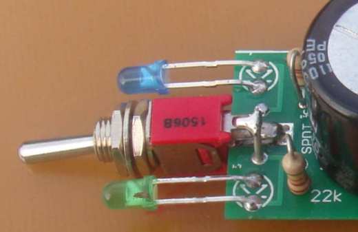
These 3 photos below clearly show how
the components are fitted and especially the switch. It is soldered with
the middle tag to the top of the board and one of the wires cut from the
1,000u electro is pushed into the hole next to the switch and bent over.
It is soldered to the top tag. The same is done under the board.
This makes the switch very firmly connected to the board.


A close-up of the switch,
showing the leads soldered to the tabs on the switch


All the components fit on the PC
board and the module comes with 2 x 1,000u electrolytics. The input can
be 12vAC to 15vAC or 20vDC to 35vDC.
This module requires a
supply of 35-36v to get the maximum output.
But you may find the output will be sufficient at 12v or 24v. This
is the first thing you will experiment with when fitting the module
to your layout.
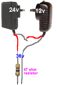
You can make a 12v 24v or 36v supply very cheaply by using 24v and
12v plug packs. These are available on eBay for less than $10.00
(combined) including postage.
If you are making 36v, simply connect the leads as shown in the
following diagram.
Some of these plug packs have a current detecting overload circuit
and "shut-down" if the current is more than 1 amp (even for a
millisecond).
To prevent this we add a 47 ohm resistor.
This only applies when you are using the plug packs for our CDU
modules (like this project) as the high current is only required for
less than a second and then falls to a very small value.
The resistor will not get warm when used in this particular
application.

CONSTRUCTION
All the parts fit neatly on the PC board.
The diodes, electrolytics and LEDs are identified on the board.
The screw terminals allow easy connection to your power
supply and point motor without the need for any additional soldering.
The cost of the module is less than buying the components from your
local electronics shop. That's because we produce the kits 20 at a time
and build them 10 at a time and pass the savings to you. We have sold
thousands of CDU modules during the past 35 years and they
will all be working perfectly.
|
PARTS LIST |
|
2 - 22k 1 - 100u 25v electrolytic 2 - 1,000u 35v 2 - 1N 4004 diodes 2 - 1N 5404 diodes 1 - 3mm blue LED 1 - 3mm green LED 2 - 3-screw terminal blocks 1 - mini toggle switch 1 - 20cm fine solder 1 - CDU with Sw - slim PC Board |
9-7-2019