|
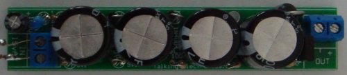
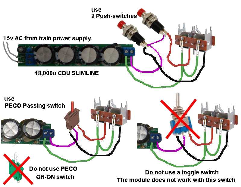
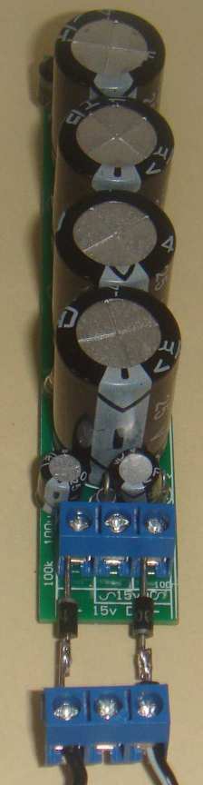
The two diagrams show how to
connect the DC and AC to the module.
The DC wires MUST be around the correct way.
The AC wires can be
around either way.
If you are sure the voltage is between 12v and 15v but not sure if
it is AC or DC, connect the two wires to the middle and lower screw
terminal (the wires can be around either way) and if the white LED
illuminates after 5-8 seconds, the voltage is AC and the CDU is
ready for use.
If it does not illuminate, the voltage is DC and now you have to be
careful.
If you have a multimeter and can prove the red wire is positive, it
is taken to the top screw terminal and the black wire to the right
screw terminal.
If you do not know the red lead is positive, you have to do the
following:
Take a power diode and screw the lead of the diode into the top
terminal so that the white stripe on the body of the diode is the
lead that goes into the terminal.
Now connect the red lead to the other lead of the diode and the
black wire to the lower terminal. If the LED does not illuminate,
reverse the wire. The LED will now illuminate. You can leave the
diode or remove it. It has been used a piece of "test gear" to
prevent damaging the module and is no longer needed.
Never reverse the leads and connect them directly to the module as
the surface mount chip on the underside of the board will BLOW UP.
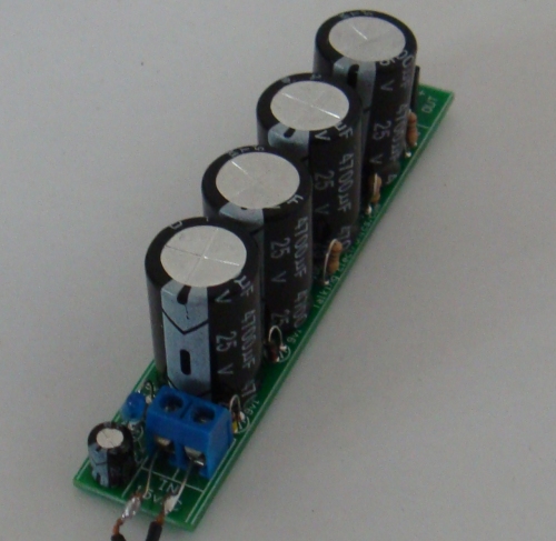
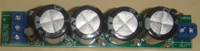
The DC input
voltage for CDU 18,000u Slimline MkII
must be 16v MAXIMUM
and each module comes with a VOLTAGE REDUCER module so you can
adjust (set) the voltage on the module to 15.5v
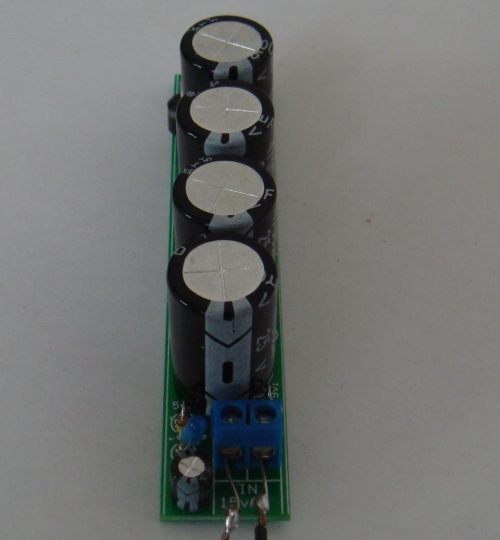
The AC voltage is not critical. It can be from 12v AC to 15v AC or
even as high as 18v AC as the
circuit will convert this to 27v and the on-board zener regulator
will reduce this to 26v across the capacitors because the excess
voltage will be sent to the LED to illuminate it very brightly. .
IF YOU HAVE A VOLTAGE between 16.5v DC and 18.5v DC, you can make or buy
the following device called a VOLTAGE REDUCE (it is included with the
fully assembled module).
VOLTAGE REDUCER
The VOLTAGE REDUCER MODULE consists of a 3-terminal block
and 4 power diodes and it screws into the 3-terminal block on the
module.
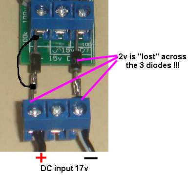
This is how the Voltage Reducer Module works: Each diode reduces
the incoming voltage by 0.75v, making a total of 3v.
When you get CDU 18,000u Slimline MkII, check the
voltage of your power supply (before touching the module) and make
sure it is less than 18v. The voltage reducer module only works for
voltages: 16v, 17v and 18v DC.
If it is 18v DC, connect the VOLTAGE REDUCER to CDU 18,000u Slimline
MkII as shown in the following image:
If the input voltage is 17v DC, you can remove one of the diodes by
soldering a link across one of them (to short it out), as
shown in the following image:
If the input voltage is 16v you can remove 2
diodes and if it is 15v, you do not need the VOLTAGE REDUCER MODULE.
If you want to deliver 15.5v DC to
CDU 18,000u Slimline - MkII with two plug packs, here
is the circuit:
An easy way to get 15.5v for
CDU 18,000u Slimline -
MkII
is with two plug packs - 5v and 12v.
You can also use three 5v plug packs and you will find many of these
in your parts-bin from old mobile
phones !!!!
|