|
CAPACITOR DISCHARGE UNIT MkII |
Capacitor Discharge Unit MkII kit is available from
Talking Electronics for $10.20 plus $6.50 postage.
Click HERE
for details.
![]()
Every
model railway has points. I don't consider a layout to be complete without at
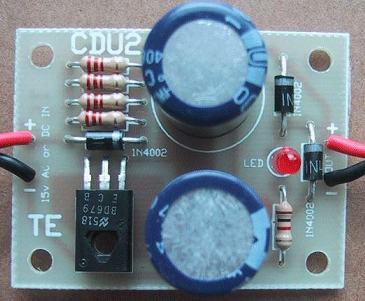
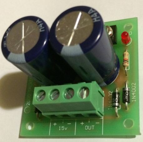
least one. Without them, the layout is a train set! The completed Capacitor
Discharge Unit MkII
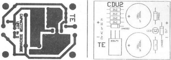
The Capacitor Discharge Unit MkII circuit
diagram.
Many of these points are switched remotely due to their distance from the operator
or inaccessibility in tunnels etc. Their method of control is usually
electrical and up to now a number of problems have been associated with these
circuits. They had the tendency to overheat the solenoids and even burn them
out. If this happened, the points, and even the track, could be damaged. The
control of a set of points is simple. Electrical energy is converted to
mechanical movement via a solenoid actuator. This device is called a 'POINT
MOTOR.' They are mounted under or near the point in such a way that the
movement sets the blades of the points for one direction or the other.
This involves a linear movement of about 5mm (1/4in). To create this movement, the simplest
device is the solenoid. It is simply a coil of wire wound on a former. Inside
the former is an iron actuator or slug which can be pulled into the coil when
the power is applied. By placing two of these coils end-to-end, a forward and
reverse motion can be created. These arrangements are called 'Switch Machines'
or 'Point Motors'.
These
two-solenoid point-motors are usually switched by short pulses of electricity.
The pulse length is often determined by the operator or by a simple
spring-loaded switch.
But there are several problems with this arrangement. Point motors require a
considerable amount of current for their operation. This means the full
capacity of the transformer will be needed. Any other items using the same
supply will suffer.
There are other problems too. The high currents will play havoc with switches. The
back emf (reverse voltage) generated by the solenoid is sometimes sufficient to
weld the switch closed. This will keep the current flowing through the solenoid
and it will overheat very quickly.
Our CAPACITOR DISCHARGE UNIT overcomes all these problems.
We have called it CDU-2 to identify it separately from our Capacitor Discharge Unit
also available from the author. Both these kits are available and the
only difference is CDU-1 uses a 2N 3055 transistor and CDU-2 uses a BD 679
Darlington transistor. Both units operate exactly the same but CDU-2 is
slightly cheaper.
Capacitor Discharge Units (CDU's) supply a high current 'burst' to the solenoid. This
current burst is over by the time the switch contacts open, thus eliminating
back emf across the switch contacts, Should a solenoid be left in circuit, the
current flowing through it (after the initial surge) will be less than 50mA. It
won't even be enough to warm the coil!
|
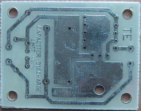
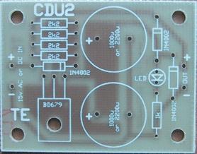
The printed circuit board: 46mm x 36mm. |
HOW DOES IT WORK?
The AC voltage (16v) at the input of the CDU is rectified by D1. This diode passes every positive half-cycle of the AC and blocks the negative half-cycle. Assuming no solenoid is connected to the CDU, R1 pulls the base of the Darlington transistor high, switching it ON and allowing current to flow through it (from C to E), to charge the 1000u capacitors. These are the reservoir capacitors that will supply the surge of current to the solenoid. D2 and D3 are protection diodes that prevent any back emf from damaging the transistor or capacitors.
This is what happens when a solenoid is connected across the output of the CDU: The reservoir capacitors will discharge through D3 into the solenoid. The low impedance of the solenoid (typically 3 ohms) is now holding the base of the transistor LOW, switching it OFF. The only current now flowing is going through R1 and the solenoid. This current is less than 50mA. The transistor remains OFF preventing the charge-current reaching the solenoid. Removing the solenoid from the output of the CDU will allow the base of the transistor to be pulled HIGH by R1. The transistor will turn on and charge the reservoir capacitors again, ready for the next operation. Recharge time is less than half a second.
CONSTRUCTION
|
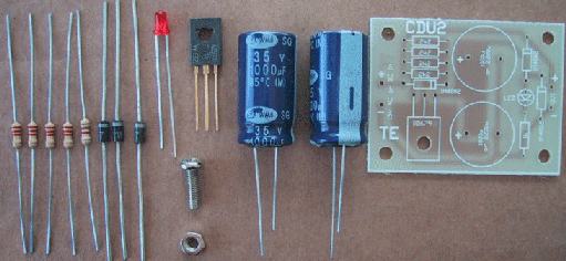
The parts |
|
PARTS LIST |
|
1 - 1k 4 - 2k2 2 - 1000u 25v - 35v. see text 3 - 1N 4002 diodes 1 - 3mm red LED 1 - BD 679 Darlington transistor 1 - nut and bolt 1 - Capacitor Discharge Unit MkII PC Board |
Assembly of the PC board is straightforward. Four 2k2 1/4watt resistors are wired in parallel to form R1. A 470R 1 watt resistor could be used but ¼ watt resistors will look much neater. The transistor is bolted to the PC board and its three leads soldered and trimmed. It requires no insulation or heatsink. The capacitors can be rated at 25v if the unit is to be operated on 15 - 16v AC. If connected to 18- 20v, the capacitors must be rated at 35vw.
Note:
Train transformers often have an output of 15v to 16v when labelled 12v, so
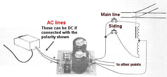
this must be taken into account. (They drop to 12v on full load). Wiring the Capacitor Discharge
Unit MkII to your point switching system.
A single 2200u capacitor can be substituted for the two 1,000u capacitors. If a more
powerful unit is required, an extra 2200u electrolytic can be added, making 2 x
2200u electrolytics.
Care must be taken with orientation of all components other than the resistors. Any error
will result in damage to some or all the components.
CONNECTING THE UNIT
Disconnect the wires of your existing system from the transformer and connect
them to the output of the CDU.
Connect the input of the CDU to the transformer. The system is now ready for operation.
See the completed wiring diagram for the connections to the capacitor discharge
unit.
The LED can be placed on the main control panel of the layout to indicate the condition of
the unit. The LED will light to indicate when the unit is ready. When a point
is operated, the LED will extinguish, then come back on when the capacitor
charges. If it remains extinguished, it indicates a fault is present and the
solenoid may be still in circuit. No other points can be operated until this is
fixed, but at least the solenoids will not be damaged!
|
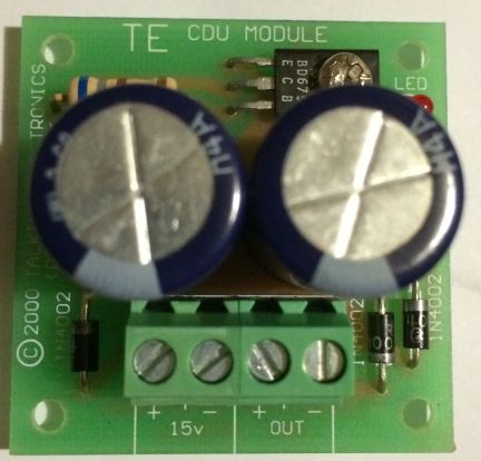
CAPACITOR DISCHARGE UNIT MkIIB |
Capacitor Discharge Unit MkIIB
kit has 2 x 2-hole
terminals to make the project easy to install.
You can build it for a friend who does not have a
soldering-iron !
$12.50 plus $6.50 postage.
Click HERE
for details.
|
PARTS LIST MkIIB |
|
1 - 1k 0.25watt 1 - 680R 1watt 2 - 2,200u 25v - 35v. see text 3 - 1N 4002 diodes 1 - 3mm red LED 1 - BD 679 Darlington transistor 1 - nut and bolt 2 - 2hole terminal blocks 1 - Capacitor Discharge Unit MkIIB PC Board |
The circuit is the same as MkII version with slightly different
resistors.
Here are some photos of the complete kit from Simon Attwell:
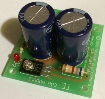
This version of the CDU (called CDU MkIIB) is available fully
assembled and tested for $2.00 extra $14.50).
All assembled CDU's have low-profile 1,000u 25v electrolytics as
only units that are less than 20mm can be posted. You can also
request 2 x 1,000u 35v electrolytics for $1.00 extra.
The extra 10v doubles the energy stored in the electrolytics as the
energy is dependent on the SQUARE of the voltage. (625
compared to 1225)
![]()