|
Charging |
No kits are available for this project
27-2-2018
One of the older type of rechargeable cell on the market is Nickel Metal Hydride (NiMH).
It has a cell voltage of 1.2v (called "Terminal Voltage" as it is the
voltage across the terminals of the cell) and a capacity higher than
previous types of cells.
Before buying any type of rechargeable cell, look at the possibility of
using Li-ion. It is a larger cell but it has a terminal voltage of 3.7v
and this means you need fewer cells to produce the required voltage.
Batteries (cells) have come a long way and to understand this cell we
need to see how it came to be.
Battery development is an evolutionary process.
Rechargeable cells started with the "Lead-Acid" cell as found in the
"Accumulator" or "Battery" of all cars in the past 100 years.
Each cell of a "Car Battery" has a cell voltage of 2.1v and contains an
electrolyte of Sulphuric Acid (H2SO4). (Not
concentrated Sulphuric acid and not weak Sulphuric acid but a fairly
strong solution.)
The battery
was charged via a Generator (A DC generating device) and later by an
alternator (An AC generating device with a set of diodes to convert the
AC to DC). As the cell
became fully charged, the electrolyte became heavier (stronger) and its Specific
Gravity (SG) could be tested with a Hydrometer (a device that looks like
a large syringe and containing a float). As the battery acid got
heavier, the float would rise higher and indicate the state of charge.
This type of cell could not be carried as the acid could easily spill
and as it charged, bubbles of Hydrogen gas (and Oxygen gas)
would be emitted from the cell through a small hole in the filler hole.
This gas is dangerous (explosive) and the release caused the
level of the electrolytic to fall in each cell and it had to be
topped up with distilled water.
The gas also contained a small amount of water vapour and carried some
of the sulphuric acid vapour into the atmosphere. This created corrosion
of any nearby metal objects and deposits of chemicals on and around the
battery. It was very messy.
The next advancement in battery technology was to gel the electrolyte so
it did not spill. The cells were also sealed so the battery could be
used in portable applications.
But charging was a problem as the gas built up in the cell and caused a
high pressure that could explode the cell. A pressure-release valve
was included but the concept was not successful until the battery chemistry
was changed by adding different elements (compounds) to the structure of
the plates so that gassing did not occur until the cell voltage was over
about 2.3v.
By providing a detecting circuit, the battery could be fully charged and
the charging current turned OFF before the cell started to "gas."
This solved nearly all the problems and the market produced a wide range of
"Gel Cells" or "Sealed Lead Acid" batteries.
But a problem remained.
If the battery was not recharged when the terminal voltage for a 12v
battery dropped to 8v, the cells started to "Sulphate" (sulphate-up).
This caused a chemical coating to be deposited on the surface of the
plates and it prevented the battery being recharged.
For example, a brand new battery left to discharge, would be completely worthless
after 12 months.
The next evolution in battery design was the NiCad, (Nickel Cadmium)
cell.
It had considerably more capacity (per unit size) than the lead acid
cell and the AA, C and D cell appeared on the market.
These cells gradually improved in performance and the capacity
increased, the robustness improved, the life of the cell increased and
cost decreased.
But one characteristic of the cell could not be altered.
The cell exhibited an effect called "Memory."
This severely changed its capacity over the life-span if the cell was
not charged correctly.
Suppose 50% of the capacity of a new cell was used in an application, and the cell was
recharged. The cell would not return to 100% capacity. It may return to
95%. If this procedure was repeated, the capacity of the cell would soon
fall to 80%, 50% and less.
To prevent this, the cell had to be discharged to zero and fully
recharged.
This could be done on special chargers with a discharge feature.
Now we come to the latest in battery technology - the Nickel
Metal Hydride cell.
This cell does not exhibit memory problems and the capacity is
considerably higher than NiCad.
But there is one very small problem.
When charging the NiMH cell, the voltage across the terminals does not
rise when the cell becomes fully charged. In fact it drops a small
amount.
This is very difficult to detect and that's the point of our discussion.
There are three ways to charge a NiMH cell. It can be "Fast Charged,"
"Slow Charged" or
"Trickle Charged."
Fast Charging refers to a charge time of 1 hour to about 4 hours.
Slow
Charging refers to a charge-time of 10-14 hours and Trickle Charging refers to a charge-time of more than
40 hours.
When ever a cell is being charged, you must deliver 150% of the capacity
of the cell, to fully charge it (when it has been completely exhausted).
Fast charging a cell involves a very high current and this causes the cell to heat up.
When the cell becomes fully charged, the charge-current is converted to a "gassing" process. The cell has the capability of re-combining the gasses but not at the rate of production during fast charging.
Re-combination of gasses creates a lot of heat and as soon as the cell becomes fully charged, it heats up considerably.
This characteristic can be detected to turn off the charger.
No cell likes to be fast charged and there is some limitation to the life of a cell that has been repeatedly fast charged.
Fast charging a single cell (of the type: 2400mA-hr AA) requires a current of about 2.4 amp. This equates to a wattage of about 2.8watts.
This means you require a 2.8watt power supply for each cell you want to charge (at the same time).
For a 10 cell battery, this requires a 28 watt power supply (plug pack). This type of plug pack is not available.
That's why fast chargers only charge 1, 2, 3 or 4 cells at a time.
There are a number of fast chargers on the market. They deliver a high current to the cell and detect the terminal voltage or the rise in cell temperature. And the cells must be taken from the equipment and fitted to the charger. These chargers are also very expensive.
For a 12v battery, 10 cells are needed and this requires a lot of work to recharge them.
Our solution is to use the SLOW CHARGE method and keep the current below the "10-hour rate" so the cells will not be damaged.
SLOW CHARGING
If the charge-current is 1/10th the ampHr rating of the cell (this is called c/10), the cells will be charged in approximately 14 hours. After this time nearly all the gasses generated in the cell will be re-combined but the pressure will not build up very slightly. For this reason, the cells must be removed from the charger after 18 hours.
TRICKLE CHARGING
If the charge current is 1/40th the ampHr rating of the cell (c/40), the gasses generated in the cell will be re-combined and the pressure will not build up.
The cell can be kept in a state of trickle charge for a long period of time without damage.
Normally, TRICKLE CHARGE was referred to as the "14-hour" charge-rate, so that a completely exhausted cell would be fully changed if the current was one-tenth the amp-hour rating of the cell. For instance, if the cell was 1.2 amp-hr, the charge current would be 120mA for 14 hours. This referred to a NiCad cell, but for a NIMH cell, the trickle charge time is "40 hours."
OUR THREE CIRCUITS
We have three circuits to charge NiMH cells. One circuit for a 12v
battery (10 cells), one for 1-8 cells at slow-charge rate and
one for 1-8 cells at Trickle Charge rate.
The first two chargers will take about 18 hours to fully charge a set of
cells and this is the maximum time allowed. The charger must be
disconnected after this time.
The third circuit will trickle charge any type or combination of cells
and the charger can be connected for long periods of time without damage
to the cells.
The circuits are very clever. They will not overload a 500mA plug pack and
not allow the cells to heat up.
CIRCUIT NUMBER 1:
This circuit will charge a 12v battery (10 NiMH
cells) @ approx 220mA.
It is a very simple circuit but requires correct setting up.
The circuit is designed around a 12vDC, 500mA plug pack. This type of
plug pack delivers about 17.5v to 18.5v DC on no-load and about 13v when the
current is 500mA.
Our circuit delivers 220mA to a set of AA cells and the output of the
plug pack is approx 16v (when 220mA flows) and the voltage across a set of 10 NiMH AA cells
is approx 13.5v during the charging process.
This gives approx 4.5v for the "head voltage," and this creates the
situation where the plug pack will deliver a current to the battery.
Firstly, you must remember, every plug pack has different
characteristics.
No two are the same and you cannot believe the specifications printed on
the package or the plug pack.
That's why you have to follow our guidelines to determine the
suitability of the plug pack you will be using.
Do not use a 300mA plug pack. It will get too hot in this application.
Some 12v DC 500mA plug packs are quite small, others are much larger.
What is the difference?
Plug packs (actually the transformer part of the plug pack) have a
hidden rating called REGULATION and for this application you
must use the biggest and heaviest plug pack you can buy.
REGULATION is the comparison of the voltage under load with the
voltage on no-load.
When the voltage under load is only slightly les than the no-load
voltage, the transformer is said to have Good Regulation.
If we take a small 12v DC 500mA plug pack, the no-load voltage may be
17.5v, but the fully loaded voltage may drop to 11.9v.
A larger 12v 500mA plug pack will have a no-load voltage of 17.5v, but
the fully loaded voltage will drop to 13.2v.
When a smaller current is drawn from the plug pack, the output voltage
is slightly higher. That's why we can use a 12v DC plug pack for this
application.
We need about 13.6v to charge 10 NiMH cells and a large 500mA plug
pack will deliver more than this voltage when the current is 220mA. The small plug
pack will not work at all.
But we can't connect a plug pack to the 12v battery without making an
important test.
You must place a multi-meter (set to 500mA or higher) in series with one
lead when the plug pack is connected to the 12v battery.
The diagram below shows you how to do this.
If the current flow is more than 260mA, you will need to reduce it
by adding a resistor in series with one lead.
In most cases, the lowest value resistor in your "parts bin" will be 10R
(brown, black, black, gold).
By placing two 10R in parallel, you will get 5R @ 0.5watt:
If you connect them in one of the leads, the current will drop
between 20mA and 40mA, depending on the type of plug pack.
You can add another pair of resistors to drop the current further, as shown
in the diagram below:
You have now produced a very simple charger for the 12v battery.
It will take up to 24 hours to charge a set of exhausted 2400mA-hr AA cells
and you will not have the worry of overcharging them.
If you have cells with a lower capacity, you will have to reduce the
current accordingly. For 1800mA-hr cells, deliver about 150mA.
For larger cells, such as C and D, you can charge them at 220mA for more
than 24 hours.
You must remember, when a plug pack is used in most situations such as a
radio etc, the current requirement varies enormously with the volume and
type of music etc.
That's why a plug pack will not normally get very hot.
But in our case, a high current is being delivered or long periods of
time and that's why you should not exceed 220mA.
CIRCUIT NUMBER 2:
This circuit will charge 1 - 8 cells @ approx 220mA. It cleverly keeps
the current at a constant 220mA, no matter how many cells are connected
and the current will remain constant as the cells charge.
CIRCUIT NUMBER 3:
This circuit will TRICKLE CHARGE 1 - 8 cells @ approx 75mA. The circuit
is adjustable from 10mA to 120mA so any type of cell can be charged.
Believe it or not, you can mix any size and type of cell with this
circuit as each will become fully charged after a period of 2 days
or more, without you having to think about the situation.
You can mix any type of cells (NiCad, Ni-MH but NOT Li-ion - see below) and any size (AA, C or D)
and they will gradually charge according their own characteristics and
capacity.
You don't have to worry about anything.
We cannot provide accurate current-flow for any of the circuits as this
will depend on the type of plug pack.
You must place an ammeter (0 - 500mA range) in one lead as shown, and
adjust the current to the desired value. The scale around the 500R pot
is not linear, so you cannot guess the current-flow. You must use a
meter to read the current.
For a set of 2400mAHr cells in TRICKLE MODE choose a current of 60mA.
HOW THE CIRCUITS WORK
The circuit uses an adjustable voltage regulator. The LM 317 range of
regulators detects 1.2v between the adjust pin and the OUT pin. In other
words, the OUT pin is always 1.2v higher than the adj pin.
Suppose the battery voltage is zero. The voltage on the
"adj" pin will be zero.
The LM 317 will produce a voltage of 1.2v on the OUT pin.
Current will flow into the battery and the voltage across the terminals
of the battery will increase. This is how the battery will get charged.
The value of the charging current will
depend on the value of "R."
The value of current can be found via the formula:

Where I is the current flowing in AMPS, V is the voltage across the
resistor (in volts) and R is the value of the resistor (in ohms).
We know the voltage is a constant 1.2v, so the formula becomes:

Suppose the value of R is 10R, the current will be
1.2/10 = 0.12A = 120mA
In the circuits above, the value of R is the resistance between
collector and emitter of the transistor. This resistance is
modified by controlling the current into the base.
As the voltage of the battery increases, the output of
the regulator increases and the current keeps flowing at a constant
120mA.
When the battery voltage reaches 13.5v, the output of the regulator will
be: 13.5v + 1.2v = 14.7v. The regulator requires approx 3.5v across it to work
correctly. This means the IN voltage must be 18.2v This is the
voltage delivered by the plug pack.
Note: The 12v DC shown on the diagrams above is only a value
indicated on the plug pack. When the voltage is measured with a
multimeter, you will find it is 17v - 18v under no-load and 13v -14v
under full load.
TRICKLE
CHARGING Li-ion CELLS
You cannot trickle charge Li-ion cells because they cannot absorb
overcharge. When fully charged, the charge current must be cut off. A
continuous trickle charge would cause plating of metallic lithium and
damage the cell.
However the TRICKLE CHARGE circuit we have developed is zener regulated
and will not rise above 20.5v for a 5-cell charger.
This allows 4.1v for each cell and corresponds to 80% charge. We are
assuming each cell will charge at the same rate and produce the same
terminal voltage but the charge-current we are providing is so low that
that nothing will overheat or explode.
The Trickle Charger circuit is designed to be left connected all the
time and will deliver about 500mA-hr to the cells per day, providing
the cells are at a state of discharge.
If they are 70% charged, they will only get an extra 10%.
The circuit is very simple and uses 2 x 12v AC to DC adaptors or a
single 24v adapter. If you supply more than 24v, the 180R
current-limiting resistors will have to be increased.
The circuit will not work with a voltage below 22v.
If the voltage across the 5 cells is 20v, the cells are 75% charged.
If the voltage across the 5 cells is 19v5, the cells are 70% charged.
The charged discussed above will charge the cell to about 95% but if you
are using the project for general-purpose work, the Trickle Charger will
be suitable.
The double-sets of diodes are needed to dissipate the heat. They
dissipate the current from the charger when the cells are charged.
The circuit is designed to deliver a maximum of 50mA and about 35mA goes
to the cells when charging and then the 50mA is passed to the zeners and
LEDs when they are charged. Each LED passes about 15mA, the maximum for
a 3mm LED.
When zeners are in a circuit and current is passing through them, the
actual voltage appearing across the zener is higher than the value
printed on it. That's why we have 9v1 and two 3v9 and white LEDs to
produce a terminal voltage of 21v3. It all depends on the current
flowing through the zener and the zener-voltage. About 0.8v is dropped
across the signal diode, leaving about 20.5 for charging the cells. All
these voltages are heavily dependent on the manufacturer of the
component and the wattage (dissipation) of the component. That's why we
have provided very large lands and tracks on the PC board, to reduce the
temperature-rise of each component.
The tiny zeners are really only about 250mW dissipation, but some
manufacturers allow 400mW and other allow 500mW. We have allowed 250mW
and that's why we have doubled-up the zener strings.
If you are going to use our own zener diodes, you will need to build the
circuit and accurately measure the output voltage with a digital meter
before connecting the Li-ion cells. The output voltage BEFORE THE
BATTERY IS CONNECTED, should be 20v5 to 20v7. This will prevent the
battery being charged above 80%. You cannot measure the output when the
battery is connected as the battery pulls the output voltage down during
the charging process.
Once you connect the Trickle Charger, you should read the voltage across
the battery after 12 hours of charging. The prototype measured 20.6v and
did not rise above this value after 2 days. This proves the circuit is
working and not allowing the battery to charge above 20.6v
You cannot measure the current entering the battery as the leads of the
multimeter will have a resistance within the meter and the charging
circuit will think the battery is 0.2v higher than it actually is. (You
will have to study what I have said . . . to understand it).
This will reduce the charging current considerably and give a false
reading.
A battery charged to 80% will still give a short-circuit current of at
least 50 amps (that is the full capability of the battery) and you are
dealing with a very dangerous item. A short circuit can create a burnt
component and even a fire, so don't have any paper or cloth anywhere
near the Power Supply when you are not in attendance.
Even a battery at 10% can deliver a high current and melt all the tracks
on the PC board. In fact the tracks are an effective "fuse" and will "go
up in smoke" when a high current flows.
Two wires touched on our prototype and melted the battery box. The smell
filled the house.
That's why we produced a printed circuit aboard and made everything neat
and compact and safe.
TRICKLE CHARGER CIRCUIT
The Trickle Charger components and PCB are included in
the kit. You need 2 x 12v adapters or a 24v adapter and you can leave
the Trickle Charger connected and not have to worry about the cells.
The 5 cells remain connected to the project ALL THE TIME and you can use
it every day as the charger will charge the cells over-night.
The Trickle Charger will only work with an input voltage of 22v to 24v.
This gives between 1v and 3v "Headroom." If the voltage is below 22v,
the battery will receive NO CHARGE. If the voltage is above 24v, the
180R resistors will get too hot.
If you want to charge individual Li-ion cells, you can use a single cell
charger:
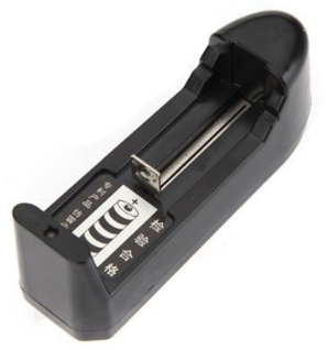
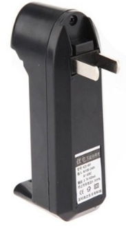
A single cell charger will look something like the images above. It will plug into the wall-socket and charge at about 70mA. These cost less than $2.00 on eBay.
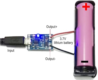
Here is a different
charging module but the hook-up is the same.
If you want to charge the cells quickly, you will have
to charge them one-at-a-time via the USB port of your computer.
This port will only deliver 1 amp and the PCB shown above will take up
to 1 amp during the initial charging of the cell.
The single cell battery box costs about $2.00 on eBay.
More details on charge Li-ion cells can be found HERE
Power Supply MkII