
save
Cheap PIC Projects
as .pdf
The PIC micro PIC12F629 is very cheap and the projects include a programmer for a desk-top computer and one for a lap-top computer - so you can do everything yourself. All the projects are backed by a kit to save you the trouble of buying the components individually. A kit costs less than sourcing the components yourself as some of the items are hard to get in small quantities.
This eBook of projects is actually a PIC Microcontroller course to teach you programming microcontrollers.
Any courses that use a language (BASIC, JAL etc) do not actually teach microcontroller programming. They don't teach how a microcontroller interprets instructions or how to write PIC instructions.
It's up to you, how you want to learn about microcontrollers. All I can say is this: No-one has produced projects similar to ours using a high-level language, so you will be on your own.
We use just the 33 instructions provided by MicroChip to program the micro and in one of the projects we used almost the entire memory of 1024 locations. This is equal to about 20 pages of program and it's amazing what can be achieved.
The main reason why we are promoting hand-coding is this: If the program doesn't work, you know the fault is in the instructions. If you use a high-level language, you are not in control of the instructions and you don't know if the fault lies in your work or the instructions that have been produced by the "language."
Our whole aim is to remove the frustration and that's why we have provided a wide range of projects and you will shown how to create your own project by taking sub-routines that have already been produced and adding extra instructions.
We also have a Library of Routines that cover almost every requirement as well as a list of hints and Ideas.
Library of terms A-E
Library of terms E-P
Library of terms P-Z
Using all these features will guarantee you success and this course is the only one of its type.
Here are the projects, but first we have an Introduction to Microcontrollers and Hints and Ideas to help you start in this field of electronics:
|
|||||||||||||||||||||||||

|
|
| PIC Instructions Explained - P3 |
|
Here
are the 33 instructions explained in words: addlw number - adds a number (called a literal - 00 to FF) to the number in the working register.
addwf FileReg, f addwf FileReg, w andlw number andwf FileReg, f bcf FileReg, bit bsf FileReg, bit btfsc FileReg, bit btfss FileReg, bit call label clrf File clrw clrwdt comf FileReg, f decf FileReg, f decfsz FileReg, f goto Label incf FileReg, f incfsz FileReg, f iorlw number iorwf FileReg, f movfw FileReg or movf
FileReg, w movlw number movwf FileReg nop option_reg retfie retlw number rlf FileReg, f rrf FileReg, f sleep sublw number subwf FileReg, f swapf FileReg, f movwf tris PORTA
or movwf trisPORTB or movwf trisio
for PIC12F629 xorlw number xorwf FileReg, f |
| PIC Instructions Explained - P4 | ||||||||||||||||||||||||||||||||||||||||||||||||||||||||||||||||||||||||||||||||||||||||||||||||||||||||||||||||||||||||||||||||||||||||||||||||||||||||||||||||||||||||||||||||||||
Here is the set of 33 instructions explained in more detail:
|
But we don't want to
scare you away so we have pre-programmed it so it's just like
using any 8-pin chip.
The fact that it can take the place of 5, 10 or even more individual
chips, turn a complex circuit into a very simple design, do things you
never thought possible, is not a reason to shy away.
To make the introduction into
microcontrollers SIMPLE AND EASY, we have given just a single page to
each project and all the rest of the 10 pages of the article can be
found on our website.
Starting is simple.
All you have to do is put it together.
Once you see how much can be done with 8 pins, you can go to the Silicon
Chip website to see the full details of the program inside the chip and
all the other details of the project.
We have provided the full listing of the program with comments on each
instruction. In addition we have provided a programmer for the chip and
the software needed to carry out the "burning" (programming) process.
We have deliberately kept everything cheap and simple to get the
beginner interested in this amazing area of electronics and by reading our on-line
articles you will be shown how to start
producing your own very simple programs to flash a LED or produce tones
and beeps.
Our concept is a "cut and paste" approach where you use a pre-made
template and add instructions from other projects or from a library.
We show how to do things in small steps and test the outcome
before adding more instructions.
In this way a complex project can be developed with the minimum of
frustration.
This is exactly the way we do things.
The project looks impressive in the end but it simply consists of
"sub-routines" that perform a particular operation, effect or task.
We do not use any "languages" (called high level languages). We only use
the 35 instructions that come with the PIC chip and these are presented
in a single-page list.
There are many ways to write a program and become a programmer and we
have taken the "beginners path."
With our method you will be programming in one night and in two nights
you will hooked - just like hundreds of other readers. Many will will never go back to designing a 5-IC
project.
Not only is a microcontroller project smaller, but it contains a chip
with a program that can be protected from prying eyes; by a feature
called CODE PROTECTION.
This makes it impossible to get the code out of the chip. If the chip is
not code-protected, it can be "read" by the same same piece of equipment
used to program the chip - we call the "burner."
By protecting your Intellectual Property, you have a product you can
sell and thus develop a business.
There are so many products that need developing.
Products such as a missing pulse detector for children vulnerable to SIDS,
timers for taking pills, gas detectors in the kitchen for town gas, and
the list goes on.
Many projects that needed 5 or more IC's can now be transferred to a
microcontroller-design.
I remember our first automatic dialler. It used cards that fitted into a
socket. The circuit used 17 chips. It could now be done with one 8-pin
microcontroller. But every phone now has a re-dial feature and many have
10 memories. So we have to think of something else. That's what you can
do. Many of the things that need an answer can be done with a simple
circuit and with a micro, you can solve even the more complex
requirements.
All the projects are backed-up with kits and a pre-programmed chip. Or you can build the circuit yourself on an experimental board and program the chip yourself . Or you can buy a kit and just put it together. The website shows you the different options. It doesn't matter if you want to do everything yourself or just put something together. The important part is getting started.
We have included the documentation on the description of the circuit as well as each instruction in the program. Plus a project for the programmer, a library of routines and data on the microcontroller.
These projects are designed to be a learning experience.
Newcomers may think a microcontroller project is "too complex," "too expensive," or "beyond capability."
But microcontrollers are the way of the future and we are here to change things.
In the following articles we are going to give you a number of projects that are cheaper than using discrete components and IC's. There are other advantages, too. The PC board is smaller and the operation of the circuit can be altered to suit different requirements by changing the instructions in the micro.
You just need some tools to start, such as a good quality soldering iron, side-cutters and a multimeter.
Here are the projects:
But in the beginning the kits for these projects contain a
pre-programmed microcontroller and everything can be soldered just like
a conventional electronics kit.
Not all projects are suited to converting to a microcontroller design but many projects that use 4 or more IC's
Here is an example of a project suitable for converting to a micro:
The project detects an incoming DTMF to turn a relay on or off (toggle mode) and up to 7 relays can be added.
In place of the 8 IC's we can use an 8-pin microcontroller and let the
program in the micro do all the work. Our design is a little simpler. It
uses up to 4 relays and any button can be pressed on the keypad.
The circuit detects a tone of short duration and waits for silence.
If a key is pressed only once, the first relay is turned on. If a key is
pressed twice with a short gap between presses, the second relay is
turned on.
3 presses turns on relay 3 and 4 presses turns on relay 4.
More than 5 presses turns all relays off and they can be individually
turned on again.
WRITING A PROGRAM
(FOR BEGINNERS)
Wack-A-Mole circuit looks simple because the micro does all the
work.
And the micro does all the work due to a program it contains.
And this program can be written by YOU if you follow our simple steps.
Writing a microcontroller program is one of the most interesting
challenges.
It can be written in many different ways.
Just like a book or novel, the sentence-structure can be impressive or
simple.
You can add instructions in a way that is easy to understand or add them
in a way that requires a considerable amount of reasoning to see how
they perform.
This is because some instructions are easy to understand and others are
complex and the layout can be "linear" or "jumping all over the place."
An example of a simple instruction is: incf count,f
This increments the count file and places the result in the file.
An example of a complex instruction is: xorwf
count,w
This exclusively OR's the contents of w with the count file and places
the result in w.
This is called a Boolean instruction or LOGIC instruction and each
corresponding bit is OR'ed and if only ONE of the bits is "1" the result
is "1."
The answer may be different with each pass of the routine and this makes
it complex or difficult to determine, when you are looking through the
lines of code. You need to work out the result so you can determine
where the micro will "jump to" in the program.
Sometimes a program can be shortened by one or two instructions by using
an instruction that performs a number of operations and has a number of
results.
However you need to know all these outcomes to be able to follow the
code and this makes it complex.
Fortunately, we have used only simple-to-understand instructions so you
can read the lines of code "like a book."
We call this LINEAR PROGRAMMING.
The program runs though a routine called MAIN and calls a number of
sub-routines. A sub-routine is any routine that is called more than once
and is presented separately so that it only needs to be written once.
We call this LINEAR PROGRAMMING.
We have only used the 35 instructions supplied with the chip and not
used any special or "underground" instructions known only to
advanced programmers and
assemblers.
As with everything you are trying to learn, if there is one thing that
is unexplained, you get lost.
The 35 instructions we are using is called MACHINE CODE or MACHINE
LANGUAGE as they can be read directly by the micro. The line of code
(called the instruction) is converted directly into a value that is loaded into
the chip. Rather than writing 100100110010, or a similar hex value:
AD068, we use a short sentence as explained above.
For example: decfsz count,f tells the micro to decrement the
count file and leave the result in the file. If the result is zero, the
next instruction is jumped-over.
You will hear a lot of discussion about the best type of programming
language to use, such as "BASIC" or "C" in place of Machine Language.
The choice is yours. All I can say is this:
You have decided to learn how to program a PIC microcontroller. All
languages other than PIC MACHINE CODE keep you one step away from
understanding how the chip operates and you are not learning anything about the codes
it reads.
This also includes the product called PIC-AXE. You are using a
programming language that can be ported to almost any microcontroller
and the code you are producing has nothing to do with a PIC micro. The
fact that a IC micro is used in some case is meter co-incidence. Almost
any micro could be used. In addition, this concept utilizes the
micro to only a fraction of its capabilities and costs 4 times more than
using a PIC chip.
Secondly, when a program does not work, you do not know if your coding
is incorrect or the instructions produced by the higher-level language
are at fault. You don't know what the high-level language has prepared
and it's very difficult to trouble-shoot.
And thirdly, you need to learn how to write in BASIC or
"C," whereas the 35 instructions that come with the PIC are available as
a table and only take a few days to learn.
The PIC chip we are using has space for 1024 lines of code and when you
consider the first 3-level chess game fitted into 1,000 lines of code
(for a Z-80), you can see how much can be achieved.
1,000 lines of code occupies more than 20 printed pages and this is
about the limit to "hand coding." But up to this level, Machine Code is
the quickest way to learn.
In our case, coding is done at the level called
mnemonics. This makes it easier for the programmer to write each line of
code and a program called an ASSEMBLER converts each line of code into
a train of "0's" and "1's."
To make it easy to read a program, it is laid out so that MAIN is at the
end and each sub-routine is placed in alphabetical order.
Tables are placed at the beginning, then delays.
We also advise to use only the minimum number of sub-routines so it is easy to follow
the flow of the program. Rather than create lots of short sub-routines,
only produce those that are more than say 10 lines. Short sub-routines
can be added to MAIN as included instructions.
But the biggest assistance to learning to program is our method of "copy
and paste."
We have provided a library of terms and a library of sub-routines as well as lots of programs and
any parts of these can be copied and placed into your program. All this can
be found on Talking Electronics website along with lessons on
programming.
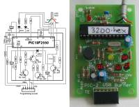
See "Start Here with PIC12F629" in the left index and you will find
the details on programming chips, including a programmer, a
connector that fits between programmer and project, prototyping boards and a
number of projects with fully explained programs.
We have everything to get you into PIC programming and the easiest way
to start is to look at the program in this project.
Contrary to popular belief, you don't "start at the beginning."
You start "at the end" by removing a few lines of code and see what
happens. Then you change a few values and see what happens. Then you add
a few lines and see what happens.
There are also a number of forums on the web that deal exclusively with
PIC micros and these are active 24 hours a day as enthusiasts from
around the world are are constantly on-line to help. Try this forum:
http://www.electro-tech-online.com/
WHY LEARN
PROGRAMMING?
After all this discussion, some readers will ask: "Why learn to
program?"
The answer is simple.
Go to a toy store and see what is on the shelves.
They have talking robots, games with LCD screens, sounds and effects
at the push of a button. Gone are the days of a flashing LED and an
amplified telephone. The toys of today include speech, InfraRed
detection, colour screens and everything to impress a child.
Most of the toys are microcontroller based and when you consider there are
millions of toys and each one is produced in the millions; the market is
enormous.
But maybe you don't want to get into the toy market.
There are lots of other fields: medical, automotive, mobile phone,
security and more.
Not only is a microcontroller cheaper than individual components but it
produces a product that is protected from copying by the fact that the
program can be "locked from prying eyes."
Even though this project is very simple it provides the gateway to
the future and once you have the capability of writing a program under
your belt, you can advance fairly quickly to more complex things.
But it is the starting point that we are famous for. Talking Electronics starts
enthusiasts in electronics.
We have always said that building a project is worth a 100 pages of
reading material and tens of thousands of hobbyists have already built
one or more Talking Electronics kits.
Now is the era of the micro and this project is the starting point. Need I
say more.
WHY PICK A PIC MICRO?
The author had a requirement to chose a micro for a project to be placed inside a greeting card. Ten different designs were developed, including a breath analyser, a game, flashing lights and similar novel ideas.
The production-run was to be 100,000 units of each and to make the project viable, it was intended to design the circuit using the cheapest micro.
After considerable investigation, the only reply from manufacturers and wholesalers was from Microchip. The simplest micros were being phased out by the other manufacturers and this left only the PIC range.
In fact PIC has a chip designed for the Chinese market and is only available in China. That's the power of the Chinese.
If you intend producing a large run of a project, a die can be made and the chip will be produced as a COB (Chip On Board), but the set-up costs makes this only viable for very large runs. In addition, you must be sure the program is "bug-free" as a chip in the form of a die cannot be altered.
However the advantage of going from a program written for a PIC chip to the same device in the form of a die means the program can be directly copied across and no further programming costs are involved.
PRINTED CIRCUIT BOARD
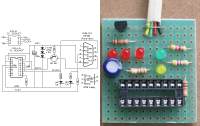
This project has been built on a PROTOTYPE PC board.
There are three reasons for this.
Talking Electronics has designed a number of projects and they are all built on the same prototype board.
This allows you to buy a number of identical boards and built any of the projects as they appear on the web or in a magazine.
The board has been designed especially for surface-mount components and allows circuits to be built and tested using these tiny devices.
As you will very quickly find out, designing a circuit for surface-mount is completely different to through-hole components and most of the time you need to produce a board before anything can be constructed.
However the cost of a producing a board is quite expensive.
Our method reduces the cost to less than 10%.
Once you start designing with surface-mount you will never go back to through-hole as the project is smaller, more-compact and appears to be simpler.
Whenever you put a lot of effort into a project, your eventual goal should be towards commercialisation and the only way to make anything economical is with surface-mount.
With this in mind we have developed a universal surface-mount prototyping board.
The parts are connected with short wires and by careful layout, you will be preparing for the eventual trackwork of the board.
Most of the prototyping boards on the market are quire useless. They don't allow a circuit to be be laid out as it will appear in a final design.
With our prototype board, you can build the circuit exactly as you want it to eventually appear and this reduces the change of a mistake.
The last thing you want is a fault.
A mistake in the layout or the program will be very difficult to locate as it is very difficult to fault-find your own work.
By doing everything in small steps, the change of a mistake creeping in is minimised.
MORE
You need to look at the enormous amount of material on Talking
Electronics website to see what can be done with a microcontroller.
A 180MB mini CD is available, filled with programming material and this
would have to be equal to a stack of books one metres high.
There are so many advantages to designing with a micro.
Apart from the professional result; it can be cheaper, quicker and
simpler.
And one of the features is the "good-size" memory.
As your code gets longer, you can call sub-routines already produced
and this makes your program more and more powerful as you get towards
the end of memory.
Of course we are not talking about Gigabytes of memory and a main-frame
computer-system.
We are talking about a project that can be really quite impressive and
could only be "dreamed-about" some 20 years ago.
One example that comes to light is a telephone dialler produced some 20
years ago. It used cards that fitted into a slot and dialed a phone
number.
The box contained 16 simple logic chips and the unit cost more than
$150.00.
This was equivalent to a weeks wages.
We can now produce exactly the same product for less than $20.00 using a
PIC chip.
However it is not needed as every phone has redial and 10 number
storage.
That's why we have to be on the look-out for new ideas. And these are
lots of them.
One idea introduces another and it's simply a matter of considering
things you will need and including elderly and sick friends and family.
All sorts of monitoring devices are needed as well as mechanical aids
and equipment.
Nearly all inventions have come about due to personal need and that's
why new tings are being invented all the time.
4 Alarm Sounds.asm
4 Alarm Sounds.hex

Below is the program written by the original designer of the project. It
is complex and contains an instruction: movlw wabl_dir_mask ;change direction
This instruction is now allowed.
Possibly it should be: movfw wabl_dir_mask ;change direction. I don't know how he was able to
compile the program. I could not assemble it.
Read through the program then look at the next program for
PIC12F629. It is shorter, easier to read, has better sounds, includes
sleep mode (100microamps) and a 3 minute timer. You can
always learn from other peoples work.
Here are some of the things to consider.
1. The second program has has fewer instructions for each sub-routine.
For instance:
decf dwell,1 ; test if dwell = 0
btfsc ZERO
has been replaced with:
decfsz dwell,1 ; test if dwell = 0
goto $-2 ;go
up the program two instructions
2. The piezo lines toggle via the following instructions:
movlw b'00100001'
xorwf GPIO,1 ;toggle bits 0 & 5
This makes GP0 and GP5 change state each time the sub-routine is
executed. You do not need to know the previous state of either line.
They change state each time the sub-routine is called.
3. Instruction: goto $+1 uses 2 cycles and saves
writing: nop nop and saves one
line of code.