|
|

This project is available on 3 different PC boards:
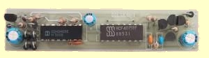
Diesel Sound 1 -long board
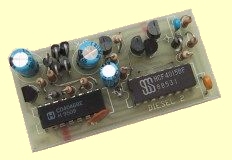
Diesel Sound 2 -short board
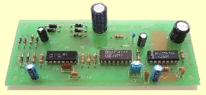
Diesel Sound 3 - called Diesel Sound 4 watt
The tiny Diesel Sound Generator easily fits into this OO scale
locomotive.
The battery is in the space over the non powered bogie,
while the speaker is below the PCB,
in a small plastic compartment, facing downwards.
Imagine having a long goods train hauled around your
layout by a beautifully detailed diesel locomotive that sounded like the
real thing. No longer do you have to tolerate the tinny whine of the
electric motor that is the real source of the locomotive's power,
because here is a project that generates a convincing diesel engine
sound.
There are three versions of the diesel sound generator so the one most
suited to your needs can be selected. Two of them are small enough to be
coaxed into HO and OO engines, or vans and box cars, helped by different
shaped PCB designs to allow for different space limitations. One of them
is long and thin, and should fit into the narrower bodies used on some
diesels. The other is for fitting into wider but shorter spaces.
Both of these printed circuit boards are very compact and use a lot of
very thin tracks. These tracks are susceptible to over or under etching
and are very easy to damage while soldering. This makes them highly
unsuitable for an inexperienced hobbyist to build. Good construction
skills are essential, as are a fine tipped temperature controlled
soldering iron and a pair of good quality side cutters.
For those who don't think you can manage the project, there is a third
version, designed to be easier to construct. The third design is
considerably larger than the other two, and is not meant to installed in
a train, but rather back at the controller. I figured as there was
little chance of coaxing a unit into an N scale loco, construction could
be made easier by spreading the components out and using thicker printed
circuit tracks. I also took the opportunity to do away with the battery
the other units require, and to install a more powerful amplifier. I
have run these diesel simulators through twelve inch speakers to great
effect.
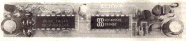
The circuit diagram of the on-board Diesel Sound Generator.
There are two different PC boards (long - called Diesel Sound 1
and short - called Diesel Sound 2) but the circuit is the same.
DIESEL SOUND 3 - 4
watt version using LM 380 chip
HOW IT WORKS
The circuit can be looked at as several parts. Some areas will differ
depending on the version. First we will consider the circuit designed to
be carried in the locomotive.
The first part is the input bridge rectifier. This makes sure power of
the correct polarity is always fed to the diesel sound generator. It
feeds power to two circuit sections. The first is the 12 volt zener
voltage regulator. C1 smoothes the output of pulse type throttles into a usable
constant voltage. D1 prevents any voltage held in the capacitor from
being fed back to the second circuit section that is connected to the
input bridge.
The second section is the speed detector. The voltage from the track is
fed to the control pin of the voltage controlled oscillator in the 4046.
As the track voltage is varied to control the speed of the locomotive,
it will also modulate the frequency of the VCO, changing the simulated
diesel's revs. So the faster the train goes, the faster the engine will
sound. As a real diesel engine contains a lot of rotating mass, the rate
at which it can rev up or slow down is limited. C3 along with its
discharge resistor R3, simulates this inertia effect.
The next section of the circuit is the pseudo-random noise generator. It
is this section that actually generates the
characteristic diesel throb. It consists of a seven stage shift register
with its two last outputs Exclusive-ORed together and fed back into its
input.
The square wave output of the VCO is used to clock the 4015 shift
register. On each positive transition of the square wave, the data that
is on pin 7 of the shift register is clocked into its first stage. At
the same time the data in the first stage is clocked into its second
stage, the data in the second stage is clocked into its third stage and
so on. The data is eventually lost when it is clocked out of the eighth
stage. The 4015 is really a dual 4 stage shift register with each stage
having its own output pin. By feeding the last output of the first shift
register into the data input of the second one, we have made an eight
stage shift register. In this circuit, the outputs are taken from stages
six and seven. The eighth stage is not used.
The Exclusive-OR gate compares outputs six and seven of the shift
register, its output reflecting what is at the input pins. If either
input is high, the output of the Exclusive-OR gate will also be high, but
if neither or both inputs are high, the output will be low. This output
is fed back into the shift register, and will soon be clocked through to
outputs six and seven again. This results in an almost random stream of
logic levels at the output of the Exclusive-Or gate. It is in fact a
repeating cycle. Varying the number of stages in the shift register will
vary the pattern. Seven stages seems to be the most suitable.
C4 and R6 are there to kick start the generator. It is possible that the
shift register will start with all of its stages containing lows. And as
a low compared with a low always gives a low, the pseudo-random sequence
will never start. C4 and R6 hold the input high long enough for one or
two highs to be clocked into the shift register. If your unit fails to
start, reduce the value of R6.
The frequency of the VCO controls the rate at which the shift register
is driven, thereby modifying the "throb" rate according to speed.
R7, R8 and C5 form a simple mixer and filter. The output of the
pseudo-random noise generator is mixed with a little of the VCO's direct
output and then the higher frequency component of the signal is shunted
to the common rail via C5, while the remaining signal is amplified and
sent to the speaker.
The VCO's direct output is used to simulate the whine of a supercharger.
If you do not require the effect, leave out the 22k resistor R7.
The battery is there to provide power when there is not enough being
picked up from the rails. D7 prevents the battery from being back fed.
The switch is there so you can shut off the battery when you have
finished running the train for the day.
If you cannot tolerate the thought of using a battery, replace C1 with a
1000uF electrolytic. The diesel sound generator will still work, but its
performance will be adversely affected. It will no longer idle and slow
speed performance will be poor, but you will never need to replace the
battery!
The other version of the diesel sound generator differs primarily in
two areas. The first is its power supply. It is fed from the rectified
output of a transformer, and because of this requires no battery.
Secondly, it uses an LM380 audio amplifier chip, giving a possible 4
watts out. With a decent speaker connected, your neighbours may think
you are playing with a REAL diesel.
Some cunning modelers will be able to graft this unit directly onto the
simple throttle presented in this book (before the reversing switch!),
and do away with the need for both bridge rectifiers and a separate
transformer. However, I recommend that a separate and isolated
transformer winding be used to power each sound generator
constructed. Usually, trying to run them off the same winding as each
other or the throttle, or even other circuits from the book, is a recipe
for disaster for the unwary. There are too many ways in which an
unexpected connection can occur, and when one does happen, either a
diode in one of the bridges, or the transformer winding itself, will be
damaged.
Diesel Sound 1
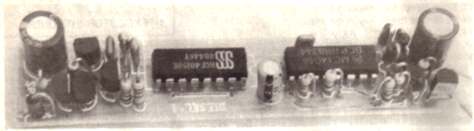
Diesel Sound 1 - photo is reverse to layout above
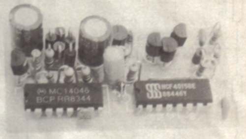
Diesel Sound 2
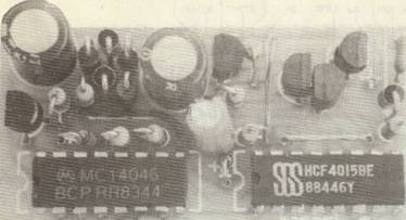
Diesel Sound 2

Diesel Sound 3
Diesel Sound 3
CONSTRUCTION
The first step is to select which board is more suited to your needs.
If you refer to the construction drawings you will see that there are
several links. The shorter ones can be tinned copper wire. The longer
ones will need to be insulated. On one version there is a link that is
actually soldered between two resistors on the top side of the board.
The chips must be soldered directly to the board. Sockets take up too
much space in a project this small. All resistors and diodes are stood
on end to conserve space. The overlay on the board shows which end the
body of the resistors should be placed. Refer to the photographs for the
physical orientation of the diodes. Only their electrical orientation is
on the overlay. The diode described as 12V is the 12 volt zener used in
the regulator.
The capacitors should all be of the monolithic ceramic or monoblock
type, once again to conserve space. Try to use small canned
electrolytics too. The size of the 100u capacitors varies a lot
depending on manufacturer and age.
The connections to the board have been put where they fit without taking
up space. The connections to the diode bridge can be made by soldering
either to the pads on the solder side of the board, or directly to the
leads of the diodes.
This version should present no problems to any
constructor, as it is neatly laid out with reasonable spaces between
components. Do not use a socket for the LM380, as it uses the copper on
the printed circuit board as a heat-sink. The copper provided for the job
is really not enough to dissipate the heat generated if the amplifier is
run flat out for extended periods of time, but I doubt anyone will.
Besides, the supply voltage is a little on the low side to allow full
output power to be attained.
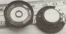
The mini speakers used in this project
COMPATIBILITY WITH THROTTLES
The diesel sound generator responds differently to various types of
throttles, I have tried it on all that were available to me at the time
of writing. As it stands, it works well on pulse type throttles. It is also completely compatible with
variable voltage throttles like that presented in Electronics for Model Railways.
However, old current controlling throttles, that is any that use a
rheostat to control speed, tend to make the diesel sound generator
over-rev. Some juggling with the input voltage divider would cure the
problem, but I have found the simplest and most effective method to be
reducing the battery voltage to six volts. The unit will be a little
quieter at idle, but will otherwise behave normally.
FITTING THINGS INTO SMALL SPACES
Obviously, if the diesel sound generator is to be built into a train, a
small speaker is required. And obtaining suitable speakers has always
been a problem too, until recently. Some companies have produced sound
effect generating key-rings, equipped with a range of bizarre "revenge"
effects, such as machine gun, death ray and grenade bomb! These gadgets
are loud. Loud enough to be heard across a sizable warehouse over the
background noise. Their secret is in their 27mm 8 ohm speaker. These
speakers are only about 9.5mm deep, too, making them almost ideal. The
good news is that these key-rings are cheap enough to buy just for the
speaker alone. As for the sound generating module, hit it with a hammer,
or toss it into the junk box, but whatever you do, don't wire it up to a
big speaker and give it to your kid I
Finding a suitable battery can be a problem too. I have found that the
diesel sound generator works best when run off a combination of power
from the rails and an internal nine volt battery. Otherwise the sound
effect stops when the locomotive does. If space is really tight, a row
of button cells could be used, but as often as not, there is plenty of
space, ft is just that the space is usually of the wrong shape to put a
standard nine volt battery into. The solution is to buy an alkaline
battery. The Duracell alkaline battery contains six very small pencil
cells that can easily be separated and tucked into odd corners through
the locomotive. Replacement will be infrequent too. There is one thing
to be careful about when using these cells. While they look similar to
"AA" cells their terminals are backwards. The negative terminal is the
stud, while the plain flat end is positive.
OBTAINING MAXIMUM VOLUME
If you are going to go to the effort of building a diesel sound generator, you will want it to be easily heard. Once you have built one up and have it driving that tiny speaker, you may find yourself wishing for a more powerful amplifier.
There is an alternate way to getting more volume from the unit. For demonstration purposes, take an empty 35mm film canister and cut a hole in the lid. The diameter of the hole should be nearly as large as that of the speaker.
With the diesel sound generator running, place the speaker, facing up, on your workbench. Now place the canister onto the speaker, so that the speaker is facing into the hole. You will notice a tremendous increase in volume as well as an increase in bass response. If you think that the bench is playing a part, lift the speaker and canister, and you will find it just as loud.
What you have just done is to provide the speaker with a resonant cavity, or simply put, a speaker box. I will not give any further details on how to arrange a suitable cavity in your locomotive. Undoubtedly, you won't find space for the canister! Experiment with building boxes to suit your locomotive from some plastic card. You may have to settle for less than optimum results due to space limitations.
PARTS
LIST |
|
1 - 270R 1 - 1k 1 - 2k2 1 - 4k7 1 - 22k 2 - 47k 1 - 220k 1 - 1M 1 - 2M2 1 - 22n monoblock 1 - 100n monoblock 1 - 220n monoblock 1 - 1u 16v electro 2 - 100u 16v electros 1 - 1N4148 6 - 1N4004 1 - 12v 400mW Zener 1 - 4015 Shift Register 1 - 4046 VCO 3 - BC547 transistors 2 - BC557 transistors 1 - mini switch 1 - 9v battery snap 1 - DIESEL 1 PCB or DIESEL 2 PCB EXTRAS: 1 - MINI SPEAKER |
PARTS
LIST |
|
1 - 2R7or2R2 1 - 10R 1 - 4k7 2 - 22k 1 - 47k 1 - 220k 3 - 1M 1 - 2M2 1 - 50k mini trim pot 1 - 330p ceramic 1 - 22n greencap 2 - 100n greencap 1 - 220n monoblock 1 - 1u 25v electro 1 - 4u7 16v electro 1 - 10u 16v electro 1 - 47u 16v electro 1 - 470u 16v electro 1 - 1,000u 25v Electro 4 - 1N4004 5 - 1N4148 1 - 4015 Shift Register 1 - 4046 VCO 1 - LM380 Audio Amp IC 1 - DIESEL Sound 3 PCB EXTRAS: 1 - 4-8R 4 Watt Speaker |
28/1/08