|
|
|
P1
P2
P3 |

This project is a miniature Audio CRO. For those not familiar with the abbreviation "CRO," it means "Cathode Ray Oscilloscope" and this is sometimes shortened to "SCOPE or O-Scope."
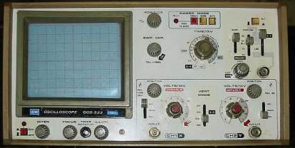
A "CRO" is a piece of test equipment with a screen. It produces a visual
indication of a waveform, via a probe, when the waveform is connected to the
input terminal of the CRO.
If you connect a microphone to the probe and whistle into the mic, the
CRO will produce a picture (trace) of the waveform. It will be in the shape of a
sinewave. The screen is very similar to an old-style TV set (called a
"picture-tube") and the picture is created by firing a beam of
electrons from the back of the tube (called the "neck'") to the front
of the tube where a layer of phosphorescent material glows when the beam
hits it.
The beam of electrons is diverted from left to right via an electromagnetic
field or an electrostatic field and this produces a line across the screen.
The beam is then deflected up or down by magnetic or electrostatic fields at 90° and this
enables it to produce all sorts of patterns.
 |
|
 |
|
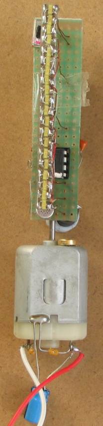 |
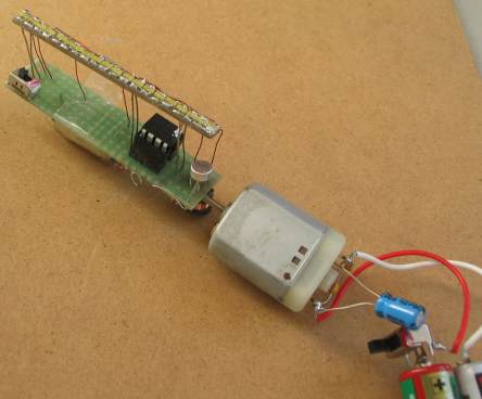
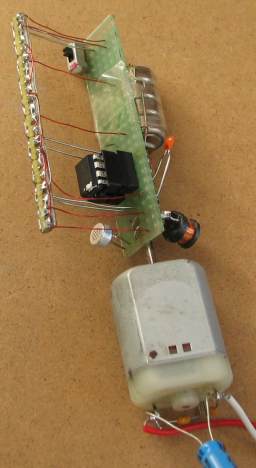
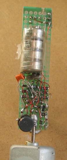
Here are some
photos of the prototype Audio CRO. Note the use of surface-mount
components allows a lot of parts to be placed in a very small
space. The 10mH inductor has been placed at an angle to make it less sensitive to the motor magnets so that it only picks up the field of the super-magnet placed on the end of the motor. The motor is actually a 12v motor from the eject mechanism of a CD player. It operates down to 3v and the RPM at 3v is very low. That's why it was chosen. There are a lot of technical challenges to overcome when electronics is combined with mechanical devices. You will experience these when you build the project. |
 |
|
This is exactly what we have done in this project. But in an extremely
miniaturised way.
Our screen is digital. It is rotating to produce a screen of light made
up of "pixels." We
have an upright strip of LEDs and this is spun from left to
right to create a screen that is 8 pixels high.
As you can see from the photos, the project is built on a small PC board
containing the PIC chip, components to interface a pick-up coil and
microphone to the chip and 4 cells. 16 LEDs are soldered to the edge of
the board to create the "display." The PC board is soldered to the shaft
of a motor and a separate 3v supply is used to rotate the motor. We have
used electro-magnetic detection to detect the starting point for each rotation
of the display so that the RPM of the motor is not important. The
display will remain absolutely steady, not matter how fast the shaft is
rotated.
However the length of the display will contract if the motor is slowed
down.
We then turn each LED on and off many times during the visual part of its
rotation, making a screen resolution of up to 8 x 60. (But the
audio section has a screen size 8 x 48). This might seem a small
area but the project is a CONCEPT DESIGN.
CONCEPT DESIGN
It is designed to show the capabilities of one of the
smallest and simplest chips in the PIC microcontroller range. It's to "get you started" and if it were a complex project, it
would
be by-passed by those who we are aiming at - the BEGINNER.
Even at this basic level there are a number of features
to challenge the brightest hobbyist - so be prepared for a really
absorbing project.
There is a generally accepted thought that the voltage across a LED is a fairly constant value. But this is not so.
As the current across it drops, the "characteristic voltage drop" also drops significantly.
For the LEDs used in this project, the voltage drops from 2.3v (when full current is flowing) to 1.66v when less than 1mA flows.
This value is important as we are placing 4 LEDs across a 5.4v supply and we need to know if any current will flow through the combination when the project is resting.
In our case, 4 LEDs at rest requires 6.64v This means no current will flow when the supply is 5.4v (it has to be higher than 5,4v for the LEDs to start to conduct).
This is the main reason why we have had to place two LEDs in series on each output. If we had only 2 LEDs from the positive rail to 0v rail, (with the output of the chip connected to the mid-point) they would illuminate when the drive-line was in "input-mode (high-impedance mode)."
THE DISPLAY
The display is made from 16 LEDs. The LEDs are in pairs and this makes 8 "pixels." Two LEDs are connected from an output to the positive rail and two LEDs to the negative rail.
When a control line is HIGH, two LEDs are illuminated and when it is LOW, the other two are illuminated. When the control line is an input, none are illuminated.
Both pairs of LEDs cannot be illuminated at the same time.
To make the display appear steady, the LEDs must be turned on at exactly the same instant, during each revolution. This is called REGISTRATION and is done by sensing the magnetic flux from a magnet and relying on the voltage produced by an amplifying transistor to be detected as a HIGH by GP3, the input-only line.
We have one further problem with displaying an audio waveform.
We need to SYNCHRONISE the rotation of the display with the audio. With a CRO, this is done via a feature called "triggering."
The beam is held at the left side of the screen until the signal reaches a certain value and this makes every waveform (called a trace) retrace the previous to produce a steady picture.
Since we cannot synchronise the audio with the rotation of the display, we have used a clever feature called SAMPLE AND HOLD.
We sample the audio to produce 48 "points" and store these in registers 30h to 5Fh.
The program then waits for the start of the next revolution and displays these 48 points. It then waits for the start of the next revolution and displays the points again. It does this 30 times and takes another sample of the audio. This produces about 2 updates every second.
The result is a very steady picture.
So, there you have it. A sample-and-hold audio CRO.
USING THE AUDIO CRO
Switch the project ON, then turn the motor on.
The display will rotate and the coil will pick up the starting-location for the display.
The words "Audio CRO" will appear on the display, then shift left. When the title has moved off-screen, you can whistle into the microphone. The chip will take a sample and store 48 pieces of data.
These will be displayed on the next rotation. The image will appear on the screen for 30 revolutions then another sample will be taken.
This allows the waveform to be viewed as a fairly steady trace.
The resolution is very low but the trace will show a sinewave and by whistling at different frequencies, you will be able to get different effects on the screen.
The whole purpose of this project is to set you up for further experimentation. We have purposely used the smallest, cheapest and simplest chip in the range to get you started.
All the help to do this is on the web.
It actually consists of hundreds of pages of files and data and everything is instantly accessible, simply by connecting to the web.
You can also access a PIC Micro webring (http://www.electro-tech-online.com/) where almost any query will be answered, 24 hours a day, by technical people around the world.
POV
We mentioned above, the chip is not able to display all the pixels at the same time, since a HIGH on an output displays one of the pixel-pairs and the LOW displays the other pixel-pair.
To create letters and pictures on the display, all the LEDs need to be illuminated at some point in time. To achieve this we create the images on the display in TWO SCANS. The first pass or scan displays all the lower pixels and the second scan displays all the upper pixels. Since the rotation of the display is fairly rapid, the two images combine and all the pixels on the screen "appear" to be displayed.
This is a result of your eye holding a previous image for a short period of time and combining it with the next.
This is the way movies and television work. It is called PERSISTENCE OF VISION (POV) and allows flickering images, above 5 flickers per second, to be combined.
PIC12F629 & PIC12F675
Talking Electronics features two of the simplest 8-pin PIC chips in
their projects. These chips are: PIC12F629 and PIC12F675.
They are identical except the PIC12F675 has four A-D channels and
PIC12F629 has none.
This project requires an A-D channel and thus the PIC12F675 has been
chosen.
The project comes with a pre-programmed chip but if you want to program
the chip yourself or alter the program, Talking Electronics website
has details of a programmer (PICkit-2), a programming socket (PC board) and an
adapter that plugs between the programmer and Programming board.
REGISTRATION
The display is made up of 8 LEDs and these are pulsed on and off very
quickly to create "pixels" and the result is an image "in the air."
To keep the image stationary we need to turn on the LEDs at the exact
same place during each revolution.
This is done with a "pick-up" coil and magnet. The flux from the magnet
produces a voltage and this is amplified by a transistor and fed to the
microcontroller as a HIGH.
This provides registration for the display and it works very well,
producing a very steady result.
But the pick-up coil is very sensitive and will detect the magnetism
from the permanent magnets of the motor.
To prevent the coil picking up the background field we have angled it to
45° and added a 100n between base and 0v. We have also reduced the gain of the transistor to 10 by adding an
emitter resistor. You need to make sure the coil detects magnetism only
once per revolution - preferably from the magnet placed on the body of
the motor.
ATTRACT MODE
When the project is turned on, the screen shows "Audio CRO" and the
letters shift left until the screen is blank.
This project is not primarily intended to show lettering
as this feature is available in another of our projects. However a
sub-routine has been included to show the capabilities of the display.
This leads us into . . .
WRITING A PROGRAM
Using a microcontroller is like being handed a blank notebook. You can
write a novel, a science report or create just
about anything on a piece of paper.
The same with a microcontroller, except the writing is done
electronically, with lines of code called instructions that are called
mnemonics, as each instruction consists of letters of a sentence, to
represent the instruction. The possibilities with a
micro as simple as the PIC12F675 are almost endless. That's why we have
pushed the boundaries with this micro to show what can be done.
The first thing to do is work out what requirements you need
and see if they fit into the capabilities of the chip.
The chip we have used has 5 in-out lines and one INPUT-ONLY line (GP3, pin4). It also
has four Analogue-to-Digital inputs, storage of data that is retained, even
when the chip is turned off (called EEPROM) and timers that hold
"count-values," as well as other features.
From a beginners standpoint it is very difficult to know what a micro
can do and the only way to generate this knowledge is to look at
projects using a particular micro and study the program.
Rather than trying to re-invent the wheel, the simplest way to start
programming is to take a pre-written project and load it into a text
editor such as NotePad2
and use it as a template.
A template contains all the data for the micro and the general layout of
the sub-routines. By keeping to a standard layout, you will be able to
find all the sub-routines as they are placed in alphabetical order, with
Tables first, then delays and Main as the last routine.
You will then be able to add your own sub-routines or "cut and paste"
them from our Library of Routines.
More on this topic can be found on Talking Electronics website in
articles such as "Start Here with
PIC12F629."
At this point we just like to mention that this project is a starting
point for lots of ideas and the screen is like a blank canvas for all
sorts of animations and effects.
PROGRAMMING IN ASSEMBLY LANGUAGE
There are a number of ways to create the program for this project. Some
require you to learn a language before programming can commence. We have
decided to use the 35
instructions that come with the microcontroller.
These instructions are easy to read as each instruction consists of
letters that represent a sentence.
This is called ASSEMBLY LANGUAGE and when you create a program in this way, you are programming in
mnemonics. A mnemonic is a set of letters or numbers that can be read by
a human and easily remembered by the programmer.
For instance, "btfss 2C,3" represents the operation: "bit test
3 in file 2C and
skip the next instruction if it is set."
All the operations for our micro can be performed using about 35
instructions.
Each line of a program contains a single instruction and just before
the micro is "burnt," a software program called an assembler
is used to change the instructions into bytes that can be read by the
micro. The assembler will produce "hex" bytes and create a file with the
extension .hex
The next piece of software you will use is called a Programmer and will
take the .hex file and convert it to binary "1's" and "0's" for
"burning" into the chip.
This process is called "programming."
Using mnemonics is called a low-level language because the instruction
can be almost directly read by the micro.
You can use higher-level languages (such as C) in which a single
instruction will perform a more-complex task than one of our mnemonic
instructions, but as you go further up the programming ladder you get
further removed from actually understanding PIC language.
Our intent is to show what can be done with a simple 8-pin PIC chip
and how a program is written.
We have made programming very simple by putting the 35 instructions in
a list and sample programs are available on Talking Electronics
website.
By copying and pasting a sub-routine (or even a single instruction), you cannot make a mistake. Just
keep to the same layout of each instruction and place them in the
correct column (the layout of a program can be seen in the
sub-routine below).
There are no syntax complications, like the order of placing brackets or
understanding what symbols like: "/, ^, &&" mean
and if you follow our guidelines of "copy and paste" and "add
one or two instructions at a time," you will have success.
HOW THE PROGRAM WORKS
The
files for this project are:
AudioCRO.asm
AudioCRO.hex
The
program is classified as "very simple" because it does not use any
complex instructions. A complex instruction is one that is "very clever"
and provides a result that is not immediately obvious.
Many of the Boolean instruction produce an answer that you have to
physically create a Truth Table to see the result. Other instructions
can shift a bit via the "carry" to another file and this is not
immediately obvious. The only instructions that need some study are
those involved with Indirect Addressing.
We have not tried to trick you with programming skills. Each instruction
is clear and obvious.
But you have to remember, we are producing a fairly elaborate result,
one that would amaze onlookers if it were presented as a 2 metre display on
a 10 metre pole. Once the concept of registration, displaying a pixel, shifting
and storing temp data is understood, the results can be expanded to any
dimension.
The program starts by setting-up the A/D converter and other
necessary "housekeeping."
The micro then goes to Main and executes a sub-routine called Attract.
At Attract, the micro constantly loops, waiting for the coil to pass the
magnet and create a HIGH on input line GP3.
As soon as a HIGH is detected, Attract creates a display 8 pixels high x
60 pixels long, by looping a program 60 times.
The width of the display is more than 300° in circumference and it is more than can be
viewed at one time. That's why the letters are shifted to the left
and eventually "drop off" the screen.
The chip is not capable of outputting all the 8 pixels at the same time so
that two passes of a program are needed to fully output the data. Pixels
1, 3, 5 and 7 are displayed on Pass-1 and pixels 2,4,6 on Pass-2. The
rotation of the display is fast enough to combine them to produce a
complete display.
To illuminate pixels for Pass-1 the output lines must be LOW. This
applies to all the LEDs we want to illuminate for the first pass and
since this is common to all the 60 bytes of data, we can place these instructions in the sub-routine.
All we have to do is determine which lines are to be made LOW. This can
be controlled by loading the "tris" register. This register determines
if a line is INPUT or OUTPUT.
If it is input, the line will be high-impedance and have no effect on
controlling a LED.
This is what we have done.
The Table contains bits for the "tris" register and it creates an
INPUT or OUTPUT. When a line is made into an INPUT, it becomes
HIGH-IMPEDANCE and does not have any effect on illuminating any LEDs.
When it is made OUTPUT, it is LOW and turns on the required LED.
This is how we turn ON the pixels we need.
Each byte in Table1 only determines values for pixels 1, 3, 5 and 7 via
GP1,2,4 and 5. The program turns on the desired LEDs and calls a short
delay to produce the width of the pixel.
Next the port-lines are turned off (made high-impedance) and a short
delay creates the gap between pixels.
The program loops 60 times to get 60 columns of data to produce what we
call the "interlace values" for "Audio CRO."
The program then goes to the second half of the routine and produces the
other 4 interlace values.
This time the bits from Table2, for the "tris" register, determine if a
line is INPUT or OUTPUT and the program makes each line HIGH. This turns
on the required LEDs. By the phenomenon of Persistence of Vision,
the result of the two half-interlaces, produces "Audio CRO."
It just happens that these two sub-routines are executed 60 times and
then the micro returns to Main where it executes the Attract sub-routine
again.
But this time a "fetch' value is introduced to the Tables and this
causes the micro to jump down the table and pick up a value and display
it as the first column. This has the effect of shifting the whole
display to the left and eventually, after 49 fetches, all the letters have
been shifted off the display.
The speed of shifting left is determined by loading the "shift" file
with "1" and this allows two half' scans to be carried out before
shifting-left.
As soon as all the wording has been shifted off the screen, the micro
goes to the next section called Main1 where it waits for the coil
to pass the magnet. This has been done so that the microphone is facing the
user. 48
samples are taken in quick succession and placed in files 30h to 5Fh.
The program then waits for registration via the coil and
outputs the 48 points on the display.
The value of each sample is obtained by a section inside the chip
(called the Analogue-to-Digital Converter) that detects the voltage on
GP0 and creates a value from 00 to 0FF (00 to 256) by charging a small
capacitor inside the chip and determining how long it takes to charge
via a resistor.
The waveform produced by the microphone and transistor amplifier is not very high and
we have taken the lowest 10 units of the A/D value to represent LED1,
the next 10 for LED 2 etc. This is not scientific nor is it accurate but
the effect is to produce a few pixels on the screen to represent a
sinewave.
The program outputs the 48 points for 30 revolutions and this produces
approx 0.5sec for each image.
If you keep whistling, the screen will update approx twice per
second.
That's the program.
It only uses 400 bytes and more than 600 bytes are still available
for adding new features.
The program can be improved in so many ways. For example, the two Tables
can be combined into one and the program picks the bits for the first
pass and then the bits for the second pass via a few transfer
instructions.
Or you can add more to the message when the project is turned on.
Instead of producing a line to show the audio waveform, you could use a
bar-graph, however this would require a double-pass; in the same way the
letters are produced in the Attract sub-routine.
There are 8 unused files that could be used to supply 8 more points for
the audio waveform.
And then there are some ideas I have not thought of.
|
MORE ON THE WEB
This project is much more complex than meets the eye. However we do not
want to deter you and that's why a pre-programmed chip is available with
the kit.
There is a lot of
detail available about using PIC chips, creating programs etc and these
can be found on the web by simply Googling PIC12F629 and/or PIC12F675.
The web is definitely the most incredible invention since "moveable
type" and since it is the result of millions of individual
contributors, you will find an enormous amount of assistance at: "PIC
Micro Webring." In addition you will find information on "Talking Electronics
Website." Click: "Fish
Shop Timer" in the left index.
PROGRAMMING THE CHIP
The chip can be programmed using either Talking Electronics
"Multi Chip Programmer" (approx $16.00) and serial cable
($6.00) or
PIC Programmer MkV (no kit for this project but its cost is less
than $10.00) or MicroChip PICkit-2 programmer
(approx $65.00) plus 5/6 pin connector ($3.00) and a programming
socket (PCB programming board - $3.50) from Talking Electronics.
Here's the run-down.
USING MULTI CHIP PROGRAMMER or PIC Programmer MkV:
The 8-pin PIC chip is taken out of the socket on the project and fitted
to the Multi Chip Programmer or
PIC Programmer MkV socket and "burnt." It is then put
back into the project.
This is very easy to do.
You must have a serial port on your computer and most old-style
computers (such as "desk-top" and "towers" have a 9-pin serial port at
the rear of the computer) for you to do this. The software to burn the
chip is IC-PROG. This is available from Talking Electronics
website as well as MPASM, NotePad2 and .inc files.
This gets you started with programming for less than $30.00.
USING PICkit-2:
If you don't have a serial port (such as for a laptop), you will need to buy the PICkit-2
programmer from Microchip (from
Modtronix in Australia) and use the USB port.
Most (all) lap-top computers have a USB port and this programmer comes
with 2 disks containing all the software you need.
This programmer is also very easy to use and works every time.
You will also need to assemble the 5/6 pin connector (from Talking
Electronics - $3.50) that connects the programmer to the project.
The PICkit-2 is available as a kit with a pre-programmed chip for the
PICkit-2 PC board from:
http://www.auelectronics.com/Hardware-CB0703.htm for approx $34.99(USD) as
BB0703 - Fully function PICkit 2
System Part#:BB0703. But the 2CD's of software are not included.
The instructions for assembly can be found here:
http://augroups.blogspot.com/2009/02/step-by-step-assembly-guide-for-cb0703.html
but the cost of the kit is very nearly the same as the fully assembled
kits from MicroChip:
http://www.microchipdirect.com/productsearch.aspx?Keywords=DV164120
(cost $50.00 USD plus postage or from
Modtronix in Australia). The PICkit-2 from MicroChip is a
"package" that also contains 2 CD's and an extra PC board that connects
to the programmer so any 8, 14 and 20 pin micros can be programmed. The
board contains 4 LEDs, a push-button and a pot as well as some
extra lands so you can create a small project.
For Australian residents, PICkit-2 can be purchased from
Modtronix
for approx $50.00 USD plus postage and
this includes 2 CD's of software. But I am not sure if the extra board
mentioned above is included in the "package."
The 5/6 pin connector that connects the programmer to our project must
be purchased from Talking Electronics $3.50 - otherwise you will have to use
the PC board (called an experimental board) that comes with the "package" from Microchip, to
hold the chip while it gets "burnt" (programmed).
20/5/2010