|
FM BUG (slug tuned) |
|
|
|
This project is a great way to learn about FM
transmission. |
This project has been designed to compete with the low-cost kits on
the market. This kit is better than all the rest.
1 and 2 transistor kits are very poor performers and it is
pointless getting a kit that does not perform.
You will be disappointed and think all FM transmitters are useless.
But that is not so.
You need 3 transistors to get reliable performance.
The first
transistor amplifies the signal from the microphone so you can hear a
pin drop.
The second transistor creates the frequency at which the bug transmits
and
The third transistor acts as an amplifier (in the form of a BUFFER), to
separate the oscillator from the antenna, so the bug does not drift when
being held.
The circuit is well-designed and includes an interesting feature: "SLUG TUNING."
We have used a steel bolt or "screw" to adjust the frequency of the
circuit and it is screwed through the board and into the coil.
By placing the first two turns close to the board, the end of the bolt
will have an effect on changing the frequency.
This is called a SLUG TUNED COIL and is one of the oldest ways to tune a
radio or transmitter.
The slug is normally ferrite but if you only insert a small portion, the
frequency will shift slightly. If the bolt is fully inserted, it will
freeze the oscillator as the coil will
pass all its energy into the bolt and the circuit will stop oscillating.
But just a small insertion will tune the bug to the frequency you want.
The approximate frequency on the 88MHz to 108MHz band is set by
expanding or compressing the 5 turn coil and then the fine tuning is
done by screwing the bold from the underside of the board. As you expand
the turns, the frequency increases and compressing the turns takes the
frequency from 88MHz to a lower frequency.
Designing a good circuit involves a number of points.
The layout of the board is important as well as the choice of actual
component values.
Our is the simplest and best design and has been perfected over the past
25 years from the sales of over 100,000 kits and 20 different designs.
Talking Electronics was the first company in the world to produce a kit
and attach a free PC board to the cover of the magazine.
This brought over 30,000 hobbyists into the market of building their own
transmitter and experiencing the clarity of FM and the enormous range
possible with only a few milliwatts of power.
These kits are very easy to build and result in an enormous achievement
with just a few components.
The fun of talking and listening is like having your own radio station
and you can transmit music from one location to another or use it to
talk over a long distance to lots of listeners.
You can use it as a "Radio Mic" at a gathering or a stage performance.
The clarity is so perfect, you will think the person is actually in the
room.
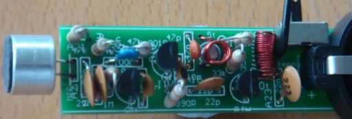
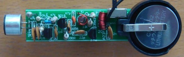
All the parts fit very neatly on the board and the only thing you
have to align is the 5 turn oscillator coil. The leads need to be bet so
they fit down the holes and the coil sits directly above the screw.
Make sure you tin the leads so the enamel is removed, BEFORE fitting the
coil down the holes.
The 20 turn coil is also pre-wound with 0.25mm wire and it is easier to
tin and fit to the board.
All the parts are in the same position as on the circuit diagram and
this makes it easy to compare the two when trouble-shooting. The
prototype-worked as soon as it was built and this is a testament to the
designs created by Talking Electronics. Over 50,000 FM Bugs have been
sold and TE has 20 different types. This is the cheapest and best and is
better than any other $8.00 bug on the market.
The screw tuning is primitive but has been used since the earliest days
of radio.
The input is amplified with a stage and the output is buffered with a
stage.
The three stages create a very sensitive transmitter that can be handled
and it will pick up the sound of a pin dropping on the floor.
HOW THE CIRCUIT WORKS
The circuit is very simple but you have to use the right-value components and put them in the correct part of the circuit to get the best results.
Many of the circuits on the web contain faults are not very reliable.
The first stage consists of a single component - the electret mic. This is actually a FET (Field Effect Transistor) and it has to have a very small current for it to operate correctly. This current is delivered by the 47k resistor.
The output is only a few millivolts but the signal is very clean and the microphone will pick up a pin dropping on the floor.
The output is connected to the next stage via a 22n capacitor.
This value is easy to obtain as a ceramic capacitor and passes about
20% of the amplitude of the signal. This is sufficient for the first
transistor in the circuit.
It amplifies the signal about 70 times to get an output of between 70mV
and 700mV.
The 22n across the power rails near the microphone prevents internal
feedback in the circuit called "Motor-boating" or squeal and the 100R
combines with the capacitor to isolates the first transistors from the
third transistor.
The second transistor is the oscillator. It gets its feedback from the
10p capacitor between the collector and emitter.
The transistor turns on via the 47k base resistor and puts a little bit
of energy into the coil and capacitor combination on the collector.
This is called a PARALLEL TUNED CIRCUIT and the capacitor gets
charged first. The coil initially refuses to allow current to flow
through it but as the capacitor charges, the coil allows current to
flow.
During this time the voltage on the collector falls and this fall passes
through the 10p to lower the voltage on the emitter and keep the
transistor turned ON.
The 10p charges during this time and the transistor turns off slightly.
This reduces the current in the coil and the magnetic field starts to
collapse and produce a voltage from the coil that is in the opposite
direction.
This puts a higher voltage on the collector and this voltage is passed
to the emitter to turn the transistor OFF slightly more.
This continues until the transistor is completely turned off and it
is similar to the transistor being removed from the circuit.
The coil continues to produce a voltage and charges the capacitor.
This voltage can be as high as 3v or more, depending on the amount of
energy it contains and the amount of energy required to charge the
capacitor to 3v.
The end result is a voltage that can be greater than 6v, however we are
not using this voltage but tapping off the emitter, where a much smaller
voltage is produced.
The emitter waveform passes through the 22p to the output stage.
This a class "A" amplifier and the signal is amplified about 50 times.
It could be grater than this due to the effect of the RFC on the
collector.
This is called a RADIO FREQUENCY CHOKE and it has the effect of
storing energy during parts of the cycle and delivering the energy
during the remainder of the cycle.
The end result is a larger output waveform.
If you connect the antenna to the collector of the oscillator
transistor, it will remove some of the energy and change the frequency
at which the circuit works. This is called "drift" and is very annoying
as the reception will be lost.
To prevent drift, we have added the 3rd transistor.
It is called a "Buffer Stage" and is designed to separate the antenna
from the oscillator.
Finally, the 22n across the power rails is deigned to tighten the rails.
This means the top rail does not move up and down when the transistor is
sending audio.
It helps to maintain the frequency at which the circuit works as the
oscillator is also called a voltage-controlled oscillator and a change
in voltage will produce a slightly different output frequency.
TUNING
Tuning is the capability of changing the frequency of the oscillator so
the bug transmits on a clear part of the band.
The FM band is completely filled with radio stations from 88MHz to
108MHz and there is almost nothing available.
The only frequency available in most large cities is 87MHz and some
radios will receive as low as 86.5MHz.
The best type of FM radio for picking up our bug is a manually tuned
radio.
This allows you to get right on top of the frequency of the bug and
achieve the greatest range.
Many of the digitally tuned radios jump in steps of 50kHz or 100kHz and
since radio stations have been allocated to these frequencies, you will be
competing with a radio station.
The 5-turn coil and the 47p produces a frequency at the lower end of the
band and screwing the slug (screw) into the coil will lower the
frequency to below 88MHz.
You have to start with the frequency above 88MHz and then
carefully reduce it without losing it below 86MHz.
The range of the transmitter is hundreds of metres with the 170cm
antenna supplied in the kit and tuning with a manually-tuned radio is simple.
Use the "tuning LED" on the radio to indicate maximum reception.
Move
the bug further away and retune the radio.
|
Screwing the slug into the coil reduces the frequency of transmission. |
RANGE
How far will this project transmit?
This circuit was placed at the top of a mountain and transmitted 27km to
the hobbyists car-radio when he got home.
This was a line-of-sight transmission and was an ideal "set-up."
We have achieved from 200 metres to 400 metres from a house to a
hand-held radio while walking down the street when there are no houses
blocking the transmission.
Some of the worst conditions are through concrete walls as they contain
mesh reinforcing that almost totally prevents the signal passing
through.
|
|
|
8/2/2017