|
FM BUG |
This kit is designed and manufactured by TALKING ELECTRONICS
For the latest price see: talkingelectronics.com
Download FM-Bug.pdf - note: the inside diameter of the coil is 3.5mm
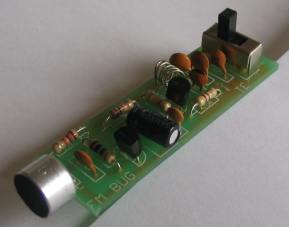
The Complete FM Bug
FM BUG Circuit
Corporate espionage is reaching new heights in
sophistication. The latest information to be released shows the depths firms
will go to pry into a rival firm's operations.
By using the latest in electronic bugging, they have stolen information, secrets
and even formulas known only to the inventors themselves.
Take the example of one firm:
Leaks from Top Management level remained a mystery until, one day, a bug was
discovered inside the Managing Director's office.
Sitting prominently on his desk was a gift box of imported cigars!
Cleverly concealed in the lower part of the box was a miniature FM transmitter .
. all a gift from a phony sales rep.
This is just one of the many bugging devices available on the eaves-dropping
market. The range includes pen and pencil holders, trophies, framed pictures and
office furniture with false bottom drawers.
These products are readily sold to fledgling companies, eager to nestle into big
brother's market.
And for a while these bugging devices worked. Few firms knew of their existence,
and even less on how to sniff them out.
But that has all changed now. If a corporation suspects a leak at any level, the
first thing they order is an investigation into security. Not only personnel,
but information and electronic security.
Debugging has grown into big business. Most large security organisations have a
section concentrating on electronic surveillance including bugging and
debugging.
They use scanners to detect hidden devices and can locate absolutely anything,
anywhere, and on any frequency.
It was only after the firm above had commissioned a scan of the entire floor,
that the cigar box was discovered. Its innocence had deceived everyone. And cost
them a small fortune!
Bugging of this kind is completely illegal and we don't subscribe to this type
of application at all.
But the uses for our SUPER-SNOOP FM WIRELESS MICROPHONE can be harmless, helpful
and a lot of fun.
Our unit is both compact and very sensitive and can be used to pick up even the
faintest of conversations or noises and transmit them 20 or so metres to any FM
receiver.
When you build the FM BUG you will see why we consider the design to be very
clever. We have used only low priced components and they are all easy to obtain.
No air trimmer capacitor is required as the coil is squeezed slightly to obtain
the desired frequency. This has allowed us to fit the bug into a tooth-brush
case so that it can be carried around or placed on a shelf.
If it is set between two books it will be hidden from view or as a supervision
accessory it can be placed on a small child, etc. The transmitted signal will
over-ride the background noise and the output will be clean. If the child
wanders beyond the range of the transmitter, the background noise will come up
and signal that the tot is out of range.
As an added bonus, you can listen to the chatterings and squabbles as the
children amuse themselves in the back yard.
It is also great for picking up the first signs of a child awakening from his
afternoon sleep or it can be used as an indicator from a bed-ridden patient.
The great advantage of the bug is the absence of wires. And since it draws only
about 5-10 milliamps, the pair of AAA cells will last for many months.
The success of this FM BUG is the use of TWO transistors in the circuit. To
create a good design, like this, each transistor should be required to perform
only one task. In any type of transmitter, there is a minimum of two tasks.
One is to amplify the signal from the microphone and the other is to provide a
high frequency oscillator.
The amplified microphone signal is injected into the oscillator to modify its
frequency and thus produce a FREQUENCY MODULATED oscillator. If an aerial is
connected to the output of the oscillator, some of the energy will be radiated
into the atmosphere.
To increase the output of our design, an RF amplifier would be needed but this
gets into legal technicalities with maximum transmitting power.
It may be of Interest to know that a record distance of 310 miles was achieved
with a 350 micro-watt transmitter in the USA, some 15 years ago. This equates to
an astounding ONE MILLION miles per watt!
In simple terms, an RF amplifier becomes a LINEAR amplifier.
We have opted for sensitivity and the first transistor is employed as a
pre-amplifier. This will enable you to pick up very low-level sounds and
transmit them about 20 to 50 metres.
MAKING THE OSCILLATOR COIL
The only critical component in the FM BUG is the oscillator coil. When I say
critical, I am referring to its effect on the frequency. Its critical nature
only means it must not be touched when the transmitter is in operation as this
will detune the circuit completely.
It is the only component which needs to be adjusted or aligned and we will cover
its winding and formation in detail.
The oscillator coil is made out of tinned copper wire and does not need any
insulation. This is not normal practice but since the coil is small and rigid,
the turns are unable to touch each other and short-out.
The coil is made by winding the tinned copper wire over a medium-size Philips
screw-driver. The gauge of wire, the diameter of the coil and the spacing
between turns is not extremely important and it will be adjusted in the
alignment stage. However when the project is fully aligned, it must not be
touched at all.
Don't be over-worried at this stage. Just follow the size and shape as shown in
the diagram and everything will come out right in the end.
THE DETAILS:
The coil has 5 turns and is wound on a 3.5mm shaft. To be more specific,
it has 5 loops of wire at the top and each end terminates at the PC
board. The coil must be wound in a clock-wise direction to fit onto the
board and if you make a mistake, rewind the coil in the opposite
direction.
CONSTRUCTION
Construction is quite straight-forward as everything is mounted on the
printed circuit board. The only point to watch is the height of some of
the components. The electrolytic must be folded over so that the board
will fit into the case.
Positioning of the parts is not as critical as you think as the final
frequency is adjusted by squeezing the coil together or stretching it
apart.
However it is important to keep the component leads as short as possible
and the soldering neat due to the high frequencies involved. The
components must be soldered firmly to the board so that they do not move
when the transmitter is being carried.
Even the poorest of soldering will work but who wants to see poor
soldering on a project?
The soldering may not affect the resulting frequency but poor layout of
the components certainly will.
All the resistors must be pressed firmly against the PC board before
soldering and the two transistors must be pushed so that they are as
closes as possible to the board.
Some BC 547 transistors will not work in the circuit. Maybe the
frequency is too high. SGS BC 547 transistors did not work at all. The
other two types: f BC 547 and Philips BC 547 worked perfectly.
All the small-value capacitors are ceramic as they are not critical in
value and do not need to be high stability. But you must be careful when
identifying them. It would be a very simple mistake to buy a 56p instead
of 5p6 because there is no difference in the size. 22n may be identified
with 223 or 22n or .022. A capacitor marked 22k will be a 22p cap and
will not be suitable. The 1n capacitor may be marked 1n or .001 or 102.
These are all the same value. The value 101 or 103 is NOT 1n so be
careful, the caps may be about the same size. The rule is: don't use a
capacitor unless its markings are clear and you are sure of the value.
The complete FM BUG
The switch is mounted on the PC board with its three terminals fitted
into the large holes.
The final items to add to the board are the two AAA cells. These come
with the kit and we have chosen them for slenderness so that they can be
fitted side-by-side.
It is very difficult to solder to the zinc case but if you roughen the
surface with a file and use a large, HOT, soldering iron, the job can be
done very quickly. Use a piece of tinned copper wire to join the
positive of one to the negative of the other. At the other end, solder
longer lengths of wire so that they can be connected directly to the PC
board. Make sure the positive terminal connects to the plus on the PC
board.
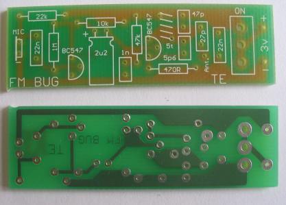
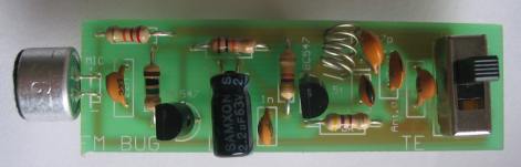
Top and bottom of the FM BUG PC
board
AAA cells are also obtainable at photographic shops. The only
alternative is an 'N' cell which is nearly as thin as an AAA cell but
only half the length.
The terminal marked A on the board is the antenna output. For a
frequency of 90MHz, the antenna should be 165cm long. This is classified
as a half-wave antenna and provides one of the most effective radiators.
If you find the antenna gets in the way you can opt for a quarter-wave
antenna and this will be 83cm long. If you only require to transmit 10
to 20 metres the antenna can be as short as 42cm or even as low as 5 or
10 cm.
The most suitable length will depend on the sensitivity of the FM radio
used to pick up the signal and the obstructions between the transmitter
and receiver. It will be a good experiment for you to 'cut' your own
antenna and determine which is the most suitable for your application.
HOW THE CIRCUIT WORKS
The circuit consists of two separate stages. The first is an audio
pre-amplifier and the second is a 90MHz oscillator.
The first stage is very simple to explain. It is a self-biasing
common-emitter amplifier capable of amplifying minute signals picked up
by the electret microphone. It delivers these to the oscillator stage.
The amplification of the first stage is about 70 and it only operates at
audio frequencies. The 22n capacitor isolates the microphone from the
base voltage of the transistor and allows only AC signals to pass
through. The transistor is automatically biased via the 1M resistor
which is fed from the voltage appearing at the collector. This is a
simple yet very effective circuit. The output from the transistor passes
through a 2.2u electrolytic. This value is not critical as its sole
purpose is to couple the two stages.
The 47k, 1n, 470R and 22n components are not critical either. So, what
are the critical components in this circuit?
The critical components are the coil and 47p capacitor. These determine
the frequency at which the bug will transmit. In addition, the effective
capacitance of the transistor plays a deciding factor in the resulting
frequency.
This stage is basically a free-running 90MHz oscillator in which the
feedback path is the 5p6 capacitor.
When the circuit is turned on, a pulse of electricity passes through the
collector-emitter circuit and this also includes the parallel tuned
circuit made up of the oscillator coil and the 47p capacitor. This pulse
of electricity is due to the transistor being turned on via the 47k
resistor in the base circuit.
When ever energy is injected into a tuned circuit, the energy is firstly
absorbed by the capacitor. The electricity will then flow out to the
coil where it is converted to magnetic flux. The magnetic flux will cut
the turns of wire in the coil and produce current and voltage which will
be passed to the capacitor.
In theory, this current will flow back and forth indefinitely, however
in practice, there are a number of losses which will cause the
oscillations to die down fairly quickly.
If a feedback circuit is provided for the stage, the natural RESONANT
frequency of the coil/capacitor combination will be maintained. The 5p6
provides this feedback path and keeps the transistor oscillating.
The 5p6 feeds a small sample of the voltage appearing at the collector,
to the emitter and modifies the emitter voltage. The transistor sees its
base-to-emitter voltage altering in harmony with the resonant frequency
of the tuned circuit and turns the collector on and off at the same
frequency.
Thus there is a degree of stability in the oscillator frequency.
The actual frequency of the stage is dependent upon the total
capacitance of the circuit and this includes all the other components to
a minor extent.
Once the basic frequency of 90MHz is set, the variations in frequency
are produced by the changes in effective capacitance of the transistor.
This occurs when its base voltage is increased and reduced. The electret
microphone picks up the sound waves which are amplified by the first
transistor and the resulting frequency is passed to the base of Q2 via
the 2.2u electrolytic.
This alters the gain of the transistor and changes its internal
capacitance. This junction capacitance modifies the oscillator with a
frequency equal to the sound entering the microphone thus FREQUENCY
MODULATING the circuit. A short length of antenna wire is connected to
the collector of the oscillator via a coupling capacitor and some of the
energy of the circuit will be radiated to the surroundings.
Any FM receiver will pick up this energy and decode the audio portion of
the signal.
SETTING UP THE TRANSMITTER
When the FM BUG is complete, checked and ready for insertion into its
case, there is one slight adjustment which must be made to align it to
the correct frequency.
As we have said, the only critical component is the oscillator coil. It
is the only item which is adjustable.
Since we are working with a very high frequency, the proximity of your
hand or even a metal screw-driver will tend to de-tune the oscillator
appreciably.
For this reason you must use a plastic aligning stick to make the
adjustment. Any piece of plastic will do. A knitting needle, pen barrel
or plastic stirring stick can be used.
Place the bug about a metre from the FM radio and switch both units on.
Tune the radio to an unused portion of the band and use the alignment
stick to push the turns of the coil together. Make sure none of the
turns touch each other as this will short out the operation of the
oscillator.
All of a sudden you will hear the background noise diminish and you may
even get feed back. This amount of adjustment is sufficient. Place the
BUG in its case and tape up the two halves.
The fine tuning between radio and transmitter is done on the radio. Peak
the reception and move the BUG further away. Peak the fine tune again
and move the BUG into another part of the house and see how far it will
transmit.
IF THE BUG FAILS
If the bug fails to operate, you have a problem. Simple digital tests
will not fix it nor will ordinary audio procedures. The frequency at
which the BUG operates is too high.
You have to use a new method called comparison.
This involves the comparing of a unit which works, with the faulty unit.
This means it is ideal for a group of constructors to build a number of
units and compare one against the other.
This will not be possible with individual constructors and they will
have to adapt this fault-finding section.
The first fact you have to establish is the correct operation of the FM
receiver.
If you have another BUG and it is capable of transmitting through the
radio you know the radio is tuned to the correct frequency. Otherwise
you will have to double-check the tuning of the dial and make sure the
radio is switched to the correct setting.
The next stage is to determine if the BUG is functioning AT ALL. The
only voltage measurements you can make are across the collector-emitter
terminals of the first transistor (1 v to 1.5v) and across the
collector-emitter terminals of the second transistor (1.3v to 1.5v)
These values won't tell you much, except that the battery voltage is
reaching the component.
Tune the radio to about 90MHz and lay the radio antenna very close to
the antenna of the BUG. Switch the BUG on and off via the slide switch.
You should hear a click in the radio if the BUG is on a frequency NEAR
90MHz. Move the turns of the aerial coil together or apart with a
plastic stick as you switch the unit ON and OFF.
If a click is heard but no feed-back, the oscillator will be operating
but not the pre-amp stage. This could be due to the electret microphone
being around the wrong way, the transistor around the wrong way, a
missing component or an open 2.2u electro.
If the fault cannot be located, compare your unit with a friend's. You
may have made a solder bridge, connected the batteries around the wrong
way, made the coil too big or used the wrong value capacitor for one of
the values.
If all this fails, put the unit aside and start again.
| PARTS
LIST 1 - 470R 1 - 10k 1 - 22k 1 - 47k 1 - 1M 1 - 5.6p ceramic = 5p6 1 - 22p ceramic or 27p or 33p 1 - 47p ceramic 1 - 1n ceramic = 1,000p or 102 1 - 22n ceramic = .022 or 223 1 - 2.2u 16v or 25v 2 - BC 547 transistors 1 - mini slide switch spdt. 1 - electret microphone (insert) 2 - AAA cells 10cm tinned copper wire 2 - metres aerial wire 1 - FM BUG PC board |
1/10/07