|
Gripper |
Gripper kit is available from
Talking Electronics for $10.00 plus $6.50 postage.
You will also need a servo and extn lead $5.50
and the parts to make the GRIPPER $3.00
Click HERE
for details.
![]()
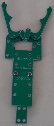
The GRIPPER in this project is constructed
from green laminate and requires a lot of care and skill to shape the components
using a hack-saw, file, sandpaper, pliers and cutters.
A set of nuts and bolts come with the arm and a sheet of instructions comes with
the kit.
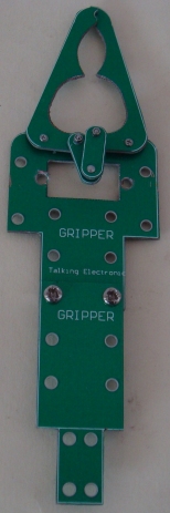
Some of the components will come partially cut-out and the rectangle cut-out has
been predrilled with fine holes so you can snip the inside and it will break
away from the surroundings. Do no "punch-out" the rectangle as the laminate will
break around the outside.
The two arms need special care and each unwanted part must be carefully broken
away in small pieces, otherwise the arm will break.
Once you have removed the unwanted bits and cut along the outside with a
hack-saw, the curved inside sections of the arms can be filed with a round or half-round file until
the through-hole plating is removed.
The curved edges and corners are smoothed with sandpaper by rubbing the arm on a sheet of
sandpaper on a table.
All the other edges are smoothed in the same way until all the components look
like those in the photo. This will take over 1 hour.
|
PARTS LIST |
|
Parts for gripper: 6 Green parts that have to cut and shaped using files, sandpaper, pliers and cutters. Set of nuts and bolts and screws |
ooooooooooooooooooooo00000000000000000000000oooooooooooooooooooooo
The GRIPPER needs a SERVO and a CONTROL
MODULE.
The Control Module is called SERVO TESTER and it also has other
names.
|
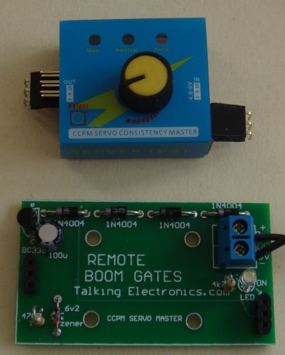
Servo Tester |
This project has 5 different names and 5
different uses.
It is also know as, and is used in these projects:
REMOTE BOOM GATES
GRIPPER
SERVO TESTER
CONTINUOUS ROTATION SERVO TESTER
POINT CONTROLLER using SERVO
(these projects are on
TalkingElectronics.com website)
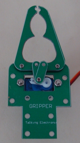
Servo fitted to Gripper
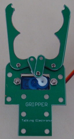
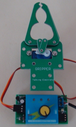
Control Module connected to Servo
Turn the knob to open and close the Gripper
The SERVO TESTER project connects a knob on a
potentiometer to a servo so you can open and close the Gripper as fast
as you turn the knob.
CCPM SERVO MODULE
The heart of the project is a SERVO CONTROL MODULE.
It is fitted to the Printed Circuit Board with stand-offs (connectors).
The images below show the CCPM SERVO MODULE.
The printed circuit board is actually a power supply to deliver 5v5 to the module
from an AC or DC voltage from 9v AC or DC, but not higher than 12v AC or DC as
the regulator transistor will get too hot.
The 90° connectors fitted to the CCPM
Module
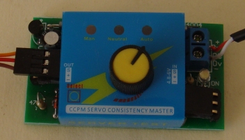
The CCPM Module fitted to the PC
board
CIRCUIT:
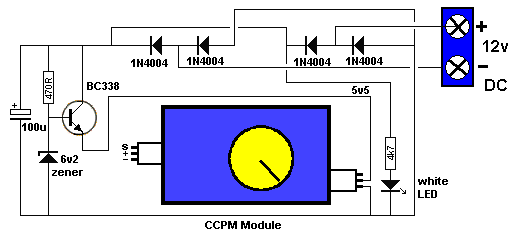
THE CIRCUIT
The heart of the project is SERVO TESTER MODULE. It
produces a set of pulses that vary in width and these are detected by the
electronics inside the servo to activate the motor. The motor turns and output
shaft that is connected to a variable resistor (potentiometer) and then the
signal from the pot is equal to the signal being received from the SERVO TESTER
MODULE, the motor stops.
The module needs a 5v supply and this has been done with components on the green
Printed Circuit Board. We have used a transistor and 5v6 zener to produce a 5v
regulated supply.
You can use a voltage from 8v to 14v DC or 6v to 12v AC and the circuit will
deliver 5v DC to the module. It has been tested with 12vAC and the transistor
gets hot, so just operate the servos for short periods.
The white LED on the board indicates the supply voltage is present.
The circuit has been drawn to follow the
components on the board to make it easy to see what the components do.
The 4 diodes are a bridge to allow either AC or DC and it does
not matter which way the power leads are connected.
Measuring the 12v supply, the circuit takes 30mA when "sitting around" and up to
100mA when the servo is operating.
EXTENSION LEAD
The kit contains components to make an extension leads, so the control knob can
be about a metre from the Gripper. The lead is a 3-wire ribbon cable
and the ends are soldered to 3-pin male and female connectors. Make sure
you mark the data wire with white paint on each of the plugs and sockets so the
leads are connected correctly.
CONSTRUCTION
All the parts fit neatly on the PC board.
The transistor, diodes, electrolytic and LED are identified on the board
and must be fitted correctly.
The screw terminals on the 2-connector block are for the power supply
leads.
HOW IT WORKS
Once everything is connected, the control knob on the CCPM
Module will turn the arm on the servo clockwise or anticlockwise at the
same speed as you turn the knob.
The module has a SELECT button that activates the servo automatically
and moves the output fully in one direction and then the other and
constantly repeats. Pushing the button again makes the servo go to
centre position and stays there.
|
PARTS LIST |
| 1 - 470R 1 - 4k7 1 - 100u 25v electrolytic 4 - 1N 4004 power diodes 1 - BC338 transistor 1 - 3mm white LED (high bright) 1 - 6v2 zener 2 - 3pin male headers 90° 2 - 3pin male headers 4 - 3pin female headers 1 - CCPM Servo Control Module with pot 1 - 2-screw connector block 1 - 20cm fine solder 1 - REMOTE BOOM GATES PC Board
for extension lead: |