HANGMAN
AN OLD GAME -
UPDATED
Page 1
P2
![]()
THIS PROJECT COVERS 7 BUILDING BLOCKS AND MAKES A VERY INTERESTING GAME FOR
TWO PLAYERS.
|
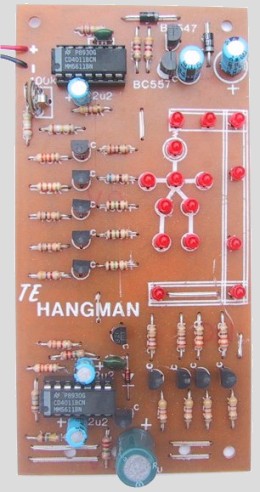
The completed Hangman. Showing the placement of all the components. |
|
The circuit diagram for the Hangman |
This is a HYBRID circuit - meaning it is composed of two different species.
We have combined transistors with IC's to achieve an update of an old game. The
complexity of the circuit comes from the repetition of the transistor stages.
Due to the number of biasing resistors required it is strongly suggested that
you use a PC board. Not only has the layout of the board been carefully
designed to make it look symmetrical when completed but it also allows the project
to go together so much easier. The boards are printed with an overlay and will
fit directly on top of a project box so the appearance looks professional. HOW THE CIRCUIT WORKS
Everybody likes re-discovering something they did years ago. Here's a game
we all played at school. Possibly under the name of HANG THE BUTCHER. The game
is quite simple. One player thinks of a word and writes down the number of
letters in that word in the form of boxes or dashes. The object of the game is
for the opponent to suggest letters of the alphabet, and if they are correct,
are placed on the dashes in the correct order so that the word gradually
appears.
To make the game more interesting, a side issue is introduced which
effectively counts the number of incorrect guesses. Each time an incorrect
letter is suggested, a systematic framework is created with straight lines in
the form of a gallows. A stick man, representing a person being hung, completes
the diagram.
The game is concluded when the correct word is created or the stick man is
completed, whichever comes first.
This is an electronic version of that game. The stick man and gallows are
made with 15 LED's and each time a TOUCH PLATE is touched, one more section of
the cartoon is illuminated.
The last LED's to be lit are 14 and 15, which represent the feet of the man.
When these LED's are at full brightness, the 8th LED begins to flash, indicating
the man is 'HANGED'.
The game can be played in two ways. The 'normal' way involves the secret
word and using the hangman to count the incorrect letters. The other suggestion
is to take it in turns illuminating the LED's until the flashing LED is set into
oscillation.
The player creating the first sign of continued flashing is the winner.
In either game, you will have lots of fun. Especially in a darkened room
where the full effect of the LED's will be produced.
The HANGMAN game consists of 7 main building blocks. These are shown in the
block diagram and are identified as follows:
|
7 BLOCKS |
|
1. 2Hz oscillator with voltage trip. 2. 2KHz multivibrator 3. Voltage doubling 4. Staircase voltage detector 5. ¼ second de-bounce 6. 1/10th second 'one shot" 7. Shut down. |
|
The Hangman Block Diagram |
When the power is applied, the only building block to come into operation is
the 2kHz multivibrator, block 2. It is made up of gates c and d of 1C2 and
feeds the push-pull buffer consisting of Q11 and Q12 to charge the 100mfd
electrolytic. The oscillator runs at a fairly high frequency and this reduces
the size of the coupling capacitor. This building block is called a VOLTAGE
DOUBLER and the voltage appearing at the output terminal is very close to
double the 9v supply minus the voltage drops across the two diodes. Under
no-load conditions this voltage appears at the output as 14v. We call this
BOOST and we have labelled it 12v BOOST because it reduces to 12 volts under
full-load conditions.
The mechanics of the voltage doubling circuit are very easy to follow. The
multivibrator c and d produces a square wave which is fed to the bases of the
two complementary transistors. When one transistor turned hard on, the other is
full off. For the first cycle, the output gate c is LOW and the BC557 is turned
ON. The negative end of the 22u is taken to the negative rail and charges
quickly via the top 1N4002 diode to 7.5v.
At the same time the 100u
electrolytic is charging to 7.6v via the two diodes. When the multivibrator
swings HIGH, the top BC547 transistor turns ON and the BC557 turns off. The
negative end of the 22u is now brought to the positive rail and its stored
7.5v will be added to that of the 100u electrolytic to bring the total
voltage up to 15.2 volts minus .7v drop across the lower diode. In fact the
voltage drop across the diodes have a double effect on reducing the voltage
since they are used for each part of the voltage doubling action. They account
for nearly 3v drop.
We must also include the collector-emitter voltage drop of
each transistor as this reduced the maximum voltage available on the 22u
boosting electrolytic. Thus the resulting voltage out of the doubler is
considerably less than you would expect. All these diode and transistor voltage
drops are constant for any voltage doubler and would obviously be less
noticeable when using higher voltages. This arrangement is capable of
delivering 15 to 20 milliamps and since it does not have a very good
regulation, the voltage under load drops to about 11 or 12 volts. This is just
enough to illuminate LED's 14 and 15 in the staircase circuit.
LED's 14 and 15 are positioned as the feet of the man being hung and are
controlled by transistor Q10. The reason for providing a voltage doubler
circuit is two-fold. It introduces a new building block into our "library" and
adds interest to the project while providing an economical way of producing the
necessary higher voltage rather than using a 12v battery.
|
Pin out for the CD 4011 |
![]()