|
3
more |
Kits are available
for the push-pull version.
Parts can be sourced from your junk-box
and mounted on
one of our prototyping matrix
boards for the circuit with constant volume:

Matrix Board 15 x
40
![]()
A HEARING AID circuit has lots of uses. It
allows you to listen to very faint sounds. The two circuits in this
article have different features with the main difference being the
impedance of the earpiece. The type of earpiece you have on hand will
determine the circuit you use.
HOW THE
CIRCUIT WORKS
The circuit above is a
direct-coupled arrangement with the initial biasing determined by the
47k and 120k resistors on the base of the first transistor.
This transistor is a common-emitter amplifier.
The voltage on the base turns the transistor ON. This causes the
resistance between the collector and emitter terminals to reduce and
allow current to flow through the 6k8 collector-load resistor and 8k2
emitter resistor.
The voltage across the 6k8 will never be more than 0.7v due to it being
between the collector and emitter terminals of a BC 557 transistor.
This means the collector of the BC 547 will sit at 3v - 0.7v =
2.3v.
The base voltage will be 2.1v and the emitter will be 1.4v
The sounds picked up by the electret microphone cause a charged mylar
diaphragm to vibrate and re-distribute some of the charges. This
re-distribution is detected by a FET
transistor (Field Effect Transistor) inside the case of the microphone and
its resistance changes.
This causes a varying current to flow and this causes a varying voltage
to appear across the 10k resistor.
This waveform is picked off the 10k resistor and becomes the volume
control for the hearing aid.
The whole circuit for this project is directly-coupled and this makes it very difficult
to diagnose and test, if something goes wrong. That's why you have to
understand the circuit fully before you start working on it with test
gear.
We have explained how the first transistor is biased via the 120k, 47k,
6k8 and 8k2 resistors.
These set the "DC bias" or "quiescent conditions" or "silent conditions" -
when no audio is passing through the circuit.
There is another 8k2 resistor on the emitter and this is called the
"negative feedback" resistor.
It also helps set the DC conditions of the circuit.
We will cover this in a moment.
The only other component in the first stage of the circuit is a 47u
electrolytic. This is designed to charge and hold its voltage at a fixed
value and keep the emitter rigid. When audio is injected into the base
of the transistor, the signal will be amplified about 50 times, with the
result appearing on the collector.
But the collector voltage does cannot change very much as the load
resistor is connected across the base-emitter junction of a PNP
transistor. So the first transistor increases the current of the signal.
The signal is now a "stronger" signal and this is necessary when
delivering a signal to the BC 557 transistor as this stage is classified
as a fairly low-impedance stage. The load for the BC557 is quite low at
470R, plus it has to move the bases of the two output transistors.
When the BC 557 turns ON, the two bases move up and the 470R pulls them
down when the BC 557 turns OFF.
The two signal diodes keep the two bases exactly 0.65v + 0.65v apart and
this just turns on the two output transistors and produces a voltage of
1.5v at their mid-point.
The output of the circuit is a very low impedance (about 20 ohms) and
this is ideal for driving a low-impedance speaker.
The output of the circuit is detected by an 8k2 resistor and this
voltage is passed back to the emitter of the first transistor.
This resistor controls the DC conditions of the circuit. It does not
feedback any of the audio as the 47u electrolytic does not respond to
audio frequencies.
To see how this feedback resistor works, you have to remember that a
transistor can be turned on by increasing the voltage on the base while
keeping the emitter fixed OR changing the voltage on the emitter while
keeping the base fixed.
In this case the base is fixed and the emitter voltage is modified.
Transistors are temperature-sensitive and if the ambient temperature
increases, the first transistor will turn ON slightly MORE and this will
turn on the BC 557.
The BC 557 will turn on more and the voltage on the two output
transistors will rise. This will increase the voltage on the
mid-point of the output of the circuit.
The increased voltage will be passed to the emitter of the first
transistor via the 8k2 feedback resistor and this will turn off the
transistor slightly.
Thus any change in the DC characteristics of the circuit will be
counter-acted by the feedback resistor.
IF IT DOESN'T WORK
If the circuit doesn't work, you
have a very big challenge as all the transistors are DC connected to
each other. This means any slight fault in the circuit will be
transferred around via the other transistors and you will not know where
the fault originates from.
So, where do you start?
The first thing you can do is check the operation of the electret mic by
placing a CRO on the output of the pot and turning it until you get a
waveform of a few millivolts when you whistle.
Next check the voltage on the base of the first transistor.
It should be 2.1v.
The voltage on the emitter should be about 0.75v less than the base and
the exact voltages are not important at the moment.
The next thing to do is remove the 8k2 feedback resistor from the output
of the circuit.
This will allow the first transistor to generate its own biasing
conditions with being upset by the feedback voltage.
Now the circuit can be tested. To do this you will need some test
equipment.
We have designed a
Logic Probe and Pulser. This produces a "beep-beep-beep" that can be
injected into the circuit and detected on the output.
HOW THE
CIRCUIT WORKS
The Hearing aid circuit above is a 3-stage arrangement, using
transistors 1, 2 and 4. The third transistor discharges a 10u
electrolytic when audio passes through the circuit and is not part of
amplifying the signal.
We will concentrate on the operation of the third transistor.
The 10u is initially charged via the 100k resistor and the voltage on the 10u is passed
to the base of the first transistor to
provide maximum gain.
When audio is passed through the circuit, any waveforms above 0.6v are
detected by the third transistor to turn it on briefly. This action
partially discharges the 10u via the 1k5 resistor. The lower voltage on
the 10u is passed to the first transistor to reduce its gain.
In this way, any loud signals are not amplified as much as weak signal
and the
circuit will pick up very faint sounds while it will not be overloaded
by loud signals.
The output is connected to high-impedance earphones.
CONSTRUCTION
The circuits can be constructed on
Matrix Board. An example of this type of board is shown above. It has
circular lands at each hole and the components are connected with very
fine tinned-copper wire, after they have been soldered in place.
ANOTHER CIRCUIT
The secret to controlling the high-gain DC coupled amplifier is the
feedback provided by the 10k resistor. The 3R3 resistor can be changed
to 2R2 to get a higher output.
Here's a
very simple circuit using a single
cell:
Amplifier circuits suitable for a hearing aid come in all sorts of
different items. This circuit comes in a toy "SPY EAR" It cost
just $5.00, at an end-of-year sale.
There is something you can learn from every circuit and this one is no
exception.
The biggest problem with any amplifier is feedback and motor-boating and
this circuit has solved the two in a very clever way.
![]()
Firstly the circuit uses a very heavy
"stage isolation" in the form of a
1k2 and 100u on the front end while the back end has no smoothing on the
supply rail.
These two components prevent ripple on the rail from entering the
microphone and first transistor.
Secondly, the microphone has a reduced voltage across it due to the 1k5
and 8k2 voltage divider network. This voltage division would have very
little effect on the gain from the microphone, however the 100n
capacitor across the microphone has a very large impact on reducing the
high frequencies picked by the microphone and prevents a considerable
amount of feedback from occurring.
The last interesting component in the circuit is the 30k. It prevents
motor-boating. Remove the resistor and see what happens!
The amplifier is built on a double-sided, plate-though-hole (PTH) PC
board with surface-mount components. It has amazing clarity and if the
100n across the microphone is removed, the circuit feeds-back almost
constantly. The only component not readily available is the 32R
earpiece. You may be able to get one from a set of earphones.
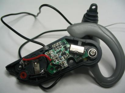
The three transistor amplifier in the "SPY" case
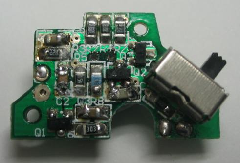
The 3-transistor amplifier
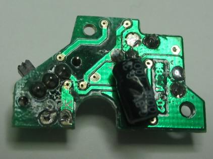
Underside of the board showing the 100u.
The 100u was damaged during manufacture.
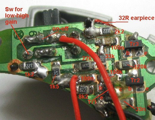
Here the board from a $2.00 SPY LISTENER:
The circuit is identical to the circuit above except the switch has two
positions. The high-gain position shorts-across the 30k (33k), thus
increasing the gain.
2111/2007