|
IR Detector |
|
|
|
This is another piece of test equipment from
Talking Electronics. |
A piece of TEST EQUIPMENT is a useless piece of junk that hangs
around the workbench until it is absolutely needed.
And that's why this project was produced. It lets you know the intensity of
an IR LED and the quality of response when it is transmitting
38kHz data. With out this project you are completely frustrated. IR LEDs don't produce any visible
illumination and you need some sort of detector to prove it is
working.
Most cameras can detect Infra-red LEDs but this project also detects
LEDs that are pulsing at 48kHz.
This is the frequency used by infra-red remote controls for TV's and
stereos etc, but there are other very close frequencies and this
detector only responds to 48kHz.
And when you have a LED pulsing at 48kHz, you need to know the
frequency is accurate. The IR LED receiver (on the end of the PC board) is
designed to detect exactly a 48kHz modulation and this allows you to
prove the transmitting IR LED is working correctly.
THE CIRCUIT:
HOW THE CIRCUIT WORKS
The circuit is very simple. It consists two different sections (2 separate circuits). A transistor and IR detector detects constant IR wavelengths and a 38kHz receiver detects 38kHz IR signals.
We call the IR receiver a MODULE as it contains many transistors, resistors and capacitors to produce a number of amplifying stages that only allows a 48kHz frequency to pass. This frequency is then compared to an internally generated 48kHz signal and when the two are identical, the output goes LOW and the LED connected to the output is illuminated.
The following is a block diagram of the stages. The BPF is a Band Pass Filter and this stage only allows a very narrow range of frequencies to emerge on the output of the block. This makes it easier for the next stages to work with the signal and produce a result.
But these's one little secret that no-one has mentioned.
The 48kHz signal from an IR transmitter must be turned ON and OFF as a constant 48kHz will not keep the output active !!!!
V4838 Vs VS1838
There are a number of manufacturers of the 38kHz receivers and some have no markings on them.
The Vishay V4838 is more expensive than the VS1838 but it does not produce false triggering in sunlight. That's why we have used it. You need to be careful when buying this component because some are not marked.
CONSTRUCTION
All the components are fitted to the board and soldered in the normal
way except two items.
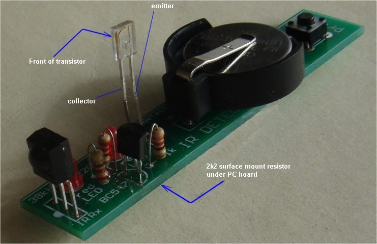
The 2k2 surface mount resistor is mounted under the board as shown in
the image above.
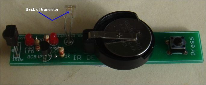
The IR receiving transistor is turned 90° after soldering, as
explained below.
The leads are very stiff.
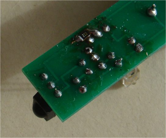
The 2k2 surface-mount resistor is soldered to the lands near the edge
of the board
This is a close-up of the IR transistor
and the 220R on the PC board
The next batch of PCB's will have 2 improvements:
The IR transistor will be turned 90°
The 2k2 will be on top of the board.
|
|
|