|
|

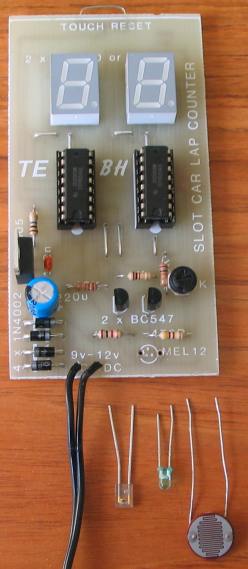
A handy 2-Digit Counter for all types of applications
![]()
This is
a low-cost 2-Digit Counter suitable for many
different applications. It was originally designed
for Slot Cars as a lap counter but slot cars have
"bitten the dust" many years ago.
However it has many other applications and you can
use it to count objects on a production-line or
people entering or leaving a room. Or even how many
times the lights are turned on and off in a room -
to check its occupancy.
It has an optical input and
when the LDR (Light Dependent Resistor) or photo
transistor receives light, the circuit is ready to
count. When the beam is broken, the circuit
increments. A 2k pot on the board adjusts the
sensitivity and the project will work with a variety
of light detectors as shown in the photo below.
The project is designed to operate from a plug pack
(9v -12v) and includes a full-wave rectifier and
7805 regulator. The input voltage can be AC or DC.
The regulator does not need a heatsink as the
project takes less than 50mA.
We tested the prototype with a 12v DC plug pack. The
voltage from the plug pack was 13.9v and the voltage
on the input of the regulator was 12.4v. The
regulator got very slightly warm. If the plug pack
is 12vAC, the DC voltage after rectification is
17-18v and the regulator gets quite hot. But it does
not need a heatsink.
The regulator can be removed and the project can be
operated from a 6v supply by connecting the positive
of the 6v supply to the "OUT" hole of the regulator
and the negative to the "COMMON" as shown in the
photo. The 100u or 220u and 4 power diodes are not
needed.
THE
CIRCUIT
The circuit is powered
from a plug pack. The output from the regulator is
5v and at this voltage the CD 4026 IC's will deliver
3-5mA per segment to the displays.
We have not used any current-limiting resistors on
the output of each chip as the current is too low to
cause any overload. The total current is
about 40mA when "88" appears on the display.
The Units chip clocks on the rising edge of the
waveform.
When the circuit is turned on and light is detected
by the LDR, its resistance is low and the first
transistor is turned on.
This causes the second transistor to turn off and
the clock pin of the second IC (pin 1) sees a HIGH.
Touching the reset pad will put "00" on the display.
When the light reaching the LDR is interrupted, its
resistance goes HIGH and the first transistor turns
off. This causes the second transistor to turn ON.
This puts a LOW on the clock pin of the units IC.
The IC does not increment during this transition.
When the LDR sees illumination its resistance goes
LOW and turns on the first transistor. The second
transistor turns off and this puts a HIGH on the
clock pin of the unit IC to increment the count.
The two transistors are in an arrangement called a
Schmitt Trigger. This has been done so that any slow
change in light level will produce a fast rise for the IC. If a slow rise is received, the
chip will begin to count very quickly when the
waveform is passing mid-voltage and this will gave a
false reading. The Schmitt arrangement increases the
waveform speed as follows:
We start the description with no illumination on the
LDR. The first transistor is not turned on the
second transistor is turned on via the 10k and 1k
base resistors. Approx 0.5v will appear across
the 1k emitter resistor and about 4.5v across the
10k collector resistor of the second transistor.
The chip will see a LOW.
As the LDR receives illumination, the first
transistor turns on and when the voltage between
collector-emitter terminal is 06v, we have a
situation where the two 10k collector load resistors
will effectively be in parallel and the 1k emitter resistor will
see nearly 1v. As the first transistor turns on
more, its collector-emitter voltage decreases to
below 0.6v and this causes the second transistor to
begin to turn off. The voltage across the 1k
resistor decreases and this effectively pulls the
emitter of the first transistor towards the 0v rail.
In other words, the first transistor is being turned
on more without any change in voltage on the base.
This causes the second transistor to turn off more
and the two change state very quickly without any
change in resistance of the LDR.
That's how the circuit produces a very fast waveform
for the IC.
The "carry" of the UNITS IC is taken to the clock of
the TENS IC to produce a 00 - 99 count.
Turning the 2k mini trim pot towards the 0v rail
makes the LDR sensitive to low levels of light.

The counter is reset by touching the "TOUCH PAD" on
the top of the project. The reset pin is high
impedance and it sees 5v via a 10M resistor. When
the reset is touched, your body removes the 5v and
both chips reset.
CONSTRUCTION
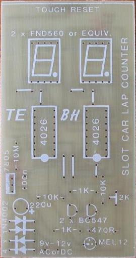
All the parts
fit on the board and you should fit the links first
then the sockets and displays.
The holes for the power diodes, regulator and mini
trim pot may have to be increased in size by using a
0.9mm or 1mm drill.
The reset pad is created from tinned copper wire so
that it is easy to touch.
The LDR is included in the kit and can be fitted via
lengths of hook-up wire and located where the
objects are to be detected.
The mini trim pot is turned fully anti-clockwise to
give the LDR maximum sensitivity.
The first photo device is an Infra-red photo
transistor. The lead on the left of this device is
the collector and it is laying with the detecting
lens UP. The second device is a photo
Darlington transistor with the collector lead is on
the left. The third device is a Light Dependent
Resistor. It can be placed either way around.
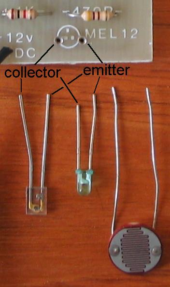
Close-up of the photo devices showing the collector
and emitter leads
and connection to the PC board
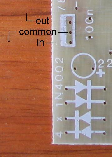
The pin-out
for the 7805 regulator
|
|
|
|
|
ADAPTING THE COUNTER
You can use a switch as the input device or create an Infra-red beam by using an Infra-red transmitting diode and the IR receiver shown in the photo above.
If you want an UP-DOWN counter, you will need to go to a
microcontroller project (Talking Electronics has a
4 digit
Up-Down Counter) or use individual chips as designed by Phil
Townsend on his website:
http://www.edutek.ltd.uk/Circuit_Pages/DualDigitCounter.html
Here is his circuit: