LEVEL CROSSING
![]()
|
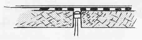
On almost every model railway there is at least one place where road and rail
cross. If prototype practice is to be followed, some way of making the crossing
safe is needed. There are several ways of doing this, including gates, booms and crossing lights. Modelling gates is fairly simple, as they are available as plastic kits, but making them operate is quite difficult, as complex gearing is needed. Operating booms have been approached in several different ways. The simplest uses the weight of the train pressing on a small bar under the track to mechanically hold down the booms. The main problems with this system are that the booms only close when the train is actually on the crossing, and often only the engine is heavy enough to hold them closed. Booms can also be actuated by solenoids or motors. For the automatic operation of these, sensors will be required to detect the presence of the train. Flashing crossing lights are another option and these require no mechanics, however they are often used in conjunction with booms. |
|
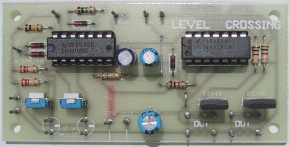
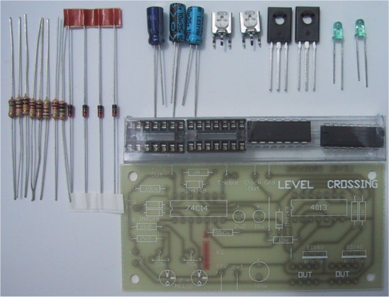
A close up of the Level Crossing, showing the placement of the components. Note the pins inserted in the PCB are to show where to connect the wires for the external components. |
|
The circuit diagram of the Level Crossing. You may not see the necessity for all the parts. They are needed when the unit is expanded. |
|
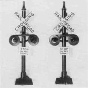
This photograph shows a pair of commercial railway crossing signals. They are available at most model railway stores. |
|
The electronics required to alternately flash two lamps is simple.
Two-transistor multivibrators are available for around ten dollars. They come
in small plastic or epoxy cases and can drive one or two crossing lights but
the only way of switching them on and off automatically is to connect them to a
spare set of contacts on a relay used in an automatic block signalling circuit. Presented here is a fully automatic light flashing unit that can detect trains coming from both directions on one track or one direction on each of two tracks. It can be expanded to cover four tracks in both directions. A crossing bell sound option can be added, as can an operating boom device. The belt sound and boom control do not work well together, as the motor driving the booms creates a lot of electrical noise, especially when driven by a pulse speed controller. Some people may find a quieter mechanism for driving the booms than the one mentioned in this article. Isolated power supplies and shielding could be used to reduce the noise level. The circuit will be described in several different stages, as each option is made on a separate PC board. The first stage will be the flashing light unit and automatic control. How It works. This unit is based on, the 74C14 Schmitt inverter and a 4013 dual D flip-flop. The operation is quite complex so it will be described in sections. The first section is the train detection circuit. The track sensor is placed on the approach to the crossing, so that the train will activate it before it arrives at the crossing. Each sensor is an MEL-12 Darlington photo-transistor. The sensitivity can be adjusted using the trimpots that feed the photo-transistor. The output from the junction of these is taken to the input of a Schmitt inverter which is part of an OR gate. When light falls on the MEL-12 it conducts, pulling the input of the Schmitt inverter low. If a train covers the MEL-12 making it dark, it turns off and the input of the Schmitt inverter is pulled high by the trimpot. The output of the MEL-12 photo-transistors are OR gated together by three Schmitt inverters two diodes and a 100K pull-up resistor. This complex type of OR gate was chosen because it had to be easily expandable and have Schmitt inputs. The output of the OR gate is fed into a delay circuit consisting of a diode, a 1M resistor, a 10u electrolytic and a Schmitt inverter, When the output of the OR gate goes high, indicating the presence of a train, the 10u capacitor is charged quickly by the diode. As long as there is a train over either photo-transistor, this capacitor will be held charged through the diode. This will hold the output of the Schmitt inverter in the delay circuit low, thus enabling the oscillator and the second D flip-flop of the 4013.
When the train is no longer over the MEL-12, it switches on and pulls the input
of the OR gate low. When both input of the OR gate are low the output will also
be low, and the 10u electrolytic will discharge through the 1M resistor.
After about 16 seconds the output of the Schmitt inverter in the delay (pin 10)
will rise, disable the oscillator end jam the output of the second stage of the
4013 HIGH. This will switch off both output transistors. |
| Shown here is the PCB track work and the overlay for the Level Crossing. |
|
The Level Crossing kit |
|
PARTS LIST |
| 2 - 1k 2 - 2k2 1 - 10k 1 - 100k 1 - 150k 1 - 1M 2 - 50k mini trim-pot 1 - 2u2 electro 1 - 10u electro 1 - 100u electro 4 - 1N4148 diodes 2 - BD140 transistors 2 - Mel 12 Darlington transistors 1 - CD40106 or 74C14 1 - CD4013 2 - 14 pin IC sockets 1 - LEVEL CROSSING PCB |
|
Construction
|
|
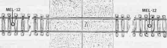
The MEL12 sensors are placed on either side of the
Level Crossing if bidirectional traffic travels along the track. The
distance between the sensor and the Level Crossing should be between 15
and 30cm. |