|
Level Crossing Lights |
9-10-2006
Every model railway has a place where road and rail meet, and when it does, some form of warning is needed. Flashing lights work well, but something is needed to drive them. And that is where this circuit comes in. All it does is flash lights and it is so simple anyone could build it!
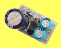
Often the first electronic accessory added to a model railway is the circuit used to drive the flashing lights at a level crossing. And that is because without electronics, crossing lights cannot be made to operate. The printed circuit board holds all eight components required to make the level crossing lamp flasher. The lamps themselves are the final components required to make this tiny module work.
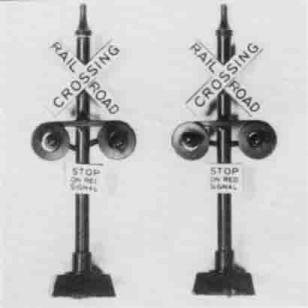
A pair of commercial railway crossing signals.
They are available at most model railway stores.
Refer to our project LEVEL CROSSING for
a fully automatic level crossing circuit capable of handling multi-track
crossings. It features an electronic twin bell sound generator, and if
required, is capable of opening and closing motorized boom gates. It
uses four printed circuit boards, allowing it to be configured to
various layouts.
This circuit is the opposite end of the
scale. It uses only eight components, all of them cheap and is very easy
to build, making it an ideal beginners project. And all it does is
flash lights. Switching it on and off must be done either by another
circuit, or a simple switch.
It is a completely stand alone project. It runs directly off the 12V to
15V AC or DC accessory outputs provided on the back of some train
controllers, making it unnecessary to build a special power supply. The
whole unit is small enough to be built into a track-side shed or relay
box, making it very easy to hide on your layout.
If this is the first project you have built, take special care with the
soldering. Don't expect it to work if there are solder bridges
and dry joints. These two soldering faults, along with incorrectly
placed components, are the biggest cause of projects not working
properly. Rarely is it actually a faulty component.
ABOUT THE CIRCUIT
The circuit is simply a two transistor astable multivibrator fed by a half wave rectifier. The lamps form the outer legs of the circuit. Without the lamps in the circuit, it won't work.
Only the positive half cycle of the AC is passed by D1. It charges the 1000u capacitor C1 as well as supplying power to the rest of the circuit. Then when the negative half cycle is being blocked by D1, the rest of the circuit runs off the charge held in C1.
Let us say that initially lamp L1 is lit. Q2 is off, allowing R2 to pull the base of Q1 high. Q1 is therefore switched on, which is why L1 is lit. C3 is being charged through L2 and the base-emitter junction of Q1. A single lamp when switched off, is about thirty ohms (30R).
Meanwhile, C2, which was charged last time Q2 was on, has had its positive end pulled down to about 0.3 volts by Q1. This means that the other end of C2 is actually negative with respect to the zero volt rail and the emitter of Q2. C2 is now discharged by R1. In fact R1 is really trying to charge the capacitor the other way around! This will continue until the negative end of C2 reaches about 0.6 volts taking the base of Q2 with it. At this point, Q2 will turn on and lamp L2 will light. It will also pull the positive end of C3 to about 0.3 volts. As C3 is now holding a charge of 12 to 15 volts, the negative end of it will be 12 to 15 volts below the zero volt rail. Thus the base of Q1 will also be at this negative potential, meaning that Q1 is now very definitely switched off. Lamp L1 will extinguish.
The whole process will now repeat itself, except the other way around. When the negative end of C3 reaches 0.6 volts, Q1 will again switch on, switching Q2 off. This "battle" will continue until the power is switched off.
The circuit's behaviour depends on the power supply used, and the number or lamps connected to it. Varying the number of lamps will change the flash rate. Changing the supply voltage also effects it. If you have the choice of either AC or DC, connecting it to the DC supply will give better results. As some train controllers don't even mark the positive and negative terminals, you will have to try it out to find the right way to connect it. If nothing happens when you first connect it, reverse the connections and try again. You cannot damage the circuit if you get it backwards as D1 will block the DC and protect the components.
If you find the lamp brightness too great, there are three possible solutions. The first is to reduce the voltage to the unit. If you can't do that, try running your lamps in series.
Refer to the diagram opposite to see how this is done. This will only work properly if all of the lamps are of the same type. If they are not, you will have to use the third method, and that is to put a resistor in line with each pair of lamps. The value of the resistor should be either 10R or 22R.
CONSTRUCTION
Construction is quite simple as there are only eight components. The resistors and diode have all been stood on end to save space. Take particular care with the orientation of the diode. It is very easy to solder a diode in backwards when it is stood on end. The orientation of the capacitors is also critical. If you put one in backwards, at best the circuit will not function correctly, the lamps fading in and out or just staying either on or off. at worst, you'll spend the next hour wiping electrolyte from the walls.
to the diagrams for the way to wire the lamps to the board. As mentioned earlier, the board is small enough to fit into a track-side hut if it is impractical for you to mount it under the layout. Just keep the wires tidy.
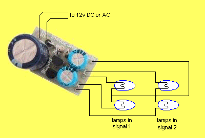
This diagram shows how the lamps would normally be wired.
Each lamp from one crossing sign is paralleled with
the corresponding lamp in the other sign.
All four lamps share the same common wire.
If one lamp blows, the circuit will continue to work.
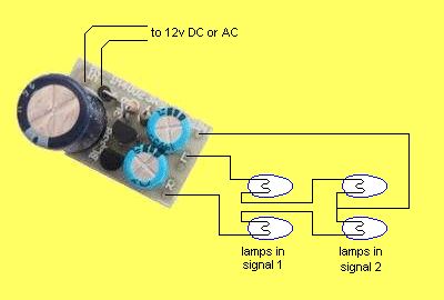
This diagram shows how the lamps could be wired
if the lamps are too
bright.
All lamps must be identical.
The lamps from one crossing sign
are wired in
series with the corresponding lamps in the other sign.
Each
string of two lamps is taken to the board common.
If one lamp blows, the
circuit will stop working.
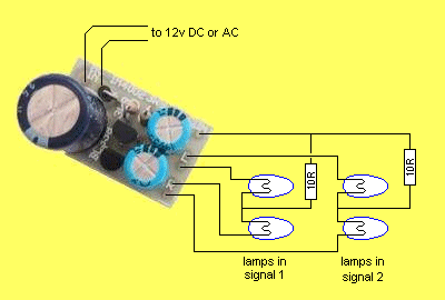
This diagram shows another way the lamps
could be wired if they are too
bright.
The circuit is similar to the first diagram, except for the
addition of a resistor in line with the common return from each sign.
The resistors should be 10 to 22 ohms depending on the lamps used.
Start
with 10R resistors. If it is still too bright, replace them
with 22R
resistors. If one lamp blows, the circuit will continue to work.
PARTS
LIST |
|
2 - 3k9 1/4 resistors 2 - 220u 25V electrolytics 1 - 1000u 25V electrolytic 1 - 1N4004 Diode 2 - BC338 Transistors 1 - Crossing PCB (X-ING) |