This project uses an 8-pin
microcontroller to produce a tumbling dice via red LEDs.
There are lots of DICE projects on the web and many of them are
copies of our original LED Dice with slowdown.
The circuit and layout has been copied by many websites and it is pleasing
to know that thousands of hobbyists have built our circuit and enjoyed its
features.
We now show how the same effect can be produced with a microcontroller and a
few resistors. The circuit is simpler, the board is smaller and the project
costs less than the original design.
That's the advantage of the microcontroller.
This project is parts of a course where we show how to design around a
microcontroller because this is the way of the future.
Once you collect the equipment necessary to burn the microcontroller, and
set-up your computer with NotePad2, to write the programs you will have 2
separate areas in your work-room.
One area will consists of a soldering iron, components and experimenter
boards, where you design and develop the project. The other area will
consist of a computer with
NotePad2, where you write the program using mnemonics (short sentences) and
compile it with MPASM to produce a .asm file as well as a .hex file.
The .hex file will then be used by WinPIC to burn the micro (program the
micro).
Take the micro from the programming socket on PIC Programmer MkIV, insert it
into the project and view the results.
This is just like designing and producing your own chip.
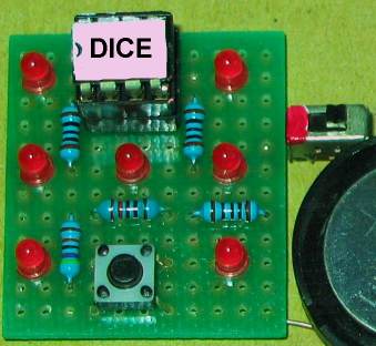
Here are some of the Dice projects and kits on the web:
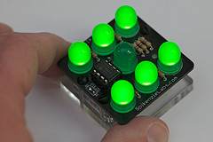
The Spikenzielabs project does not
have a "rolling effect."
The piezo under the board
is tapped to change the LEDs.
It is a $20.00 soldering project.
The .asm program is very messy
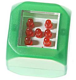
This $13.00 LED Dice from
lightinthebox.com
is already built and
does not teach any electronics.
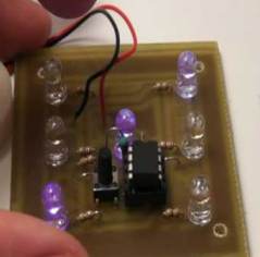
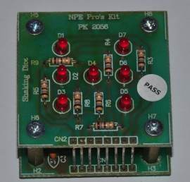
Another LED Dice project but no
program provided
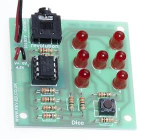
This project uses the same chip as our
project but
the PICAXE 08M chip is already programmed with
routines and costs more than $5.00
You select the routines from a list to create a program
but you are not "PIC programming."
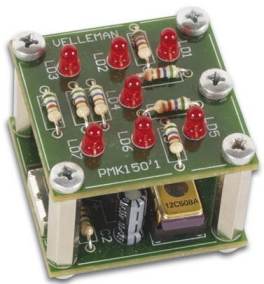
A Velleman kit. They are trying to
sell old technology!! Note the
"windowed" PIC chip!!!!!
This kits costs about $18.00 but the
microcontroller is unknown.
A LED Dice project constructed on
Matrix Board.
Only the .hex file is provided.
This project uses ATTiny-13 micro.
The PC board should have current-limiting resistors.
The display does not have a "rolling Dice" effect.
Another ATTiny-13 micro LED Dice project
A nice layout showing how to add surface-mount components.

This is the front page from a Silicon
Chip project
but the remainder of the article cannot be located.
None of the Dice projects
on the web teach how to create a program and they are simply soldering
exercises.
Ours is an EDUCATIONAL PROJECT.
We explain every instruction in the program so you can use them in the next
project you are developing.
Here's an interesting comment from
Doug Jackson,
writing for Silicon Chip:
Let’s settle an argument before it starts. Die or Dice?
Sure, the Oxford Dictionary would have us say one die, two dice. But every
man and his dog uses the word "dice" for both singular and plural. So we’ll
stick with dice.
Using a PIC allows us to significantly simplify our dice circuit. Previous
designs have typically used at least two ICs, four or more transistors and
many resistors and capacitors.
This project an ideal way for a beginner in micros to get a grasp of the
fundamentals.
The 8-pin PIC micro we are using has 6 input-output lines and one line that
is INPUT-ONLY.
We will use the input line for the switch and 4 of the other lines as
OUTPUTS.
Each output line can deliver 25mA. This limitation is due to the FET
transistors inside the the chip. Obviously they are microscopic and 25mA is
a great achievement. Many of the other microcontrollers can only deliver
20mA per drive-line.
DRIVE CURRENT
Drive Current is the current delivered to each LED to make it
illuminate.
There is a very wide range of LEDs on the market, from surface-mount, to 3mm
to 5mm and they range from very poor quality to bright, high-bright and
super bright.
Some LEDs require 20mA to produce good illumination while others produce a
very good output with as little as 2 to 5mA.
On top of this, different colour LEDs have a different characteristic
voltage-drop across them when illuminated and all these factors have to be
taken into account when determining the value of the current-limiting
resistor for each output.
One output has a single LED while the other outputs have two LEDs in series.
The value of dropper resistor for the single LED can range from
R for a red LED requiring 5mA, to R for an orange LED requiring 20mA.
We have selected 68R for the 2 LEDs in series to provide about 10mA and 82R
for the single LED to provide about 20mA.
Look at the illumination; decide which value is most suitable and adjust the
current accordingly.
Red LEDs drop about 1.7v when illuminated, orange LEDs about 2v, and green
LEDs about 2.3v.
This value does not change if the LED is surface-mount or 5mm, but it does
change slightly when the current is increased.
THE PIC DICE PROJECT
This project is very simple because all the features are
contained in the microcontroller in the form of a program.
Instead of a two chips and a lot of surrounding timing components, as in
previous LED Dice projects, we have a
single chip driving the 7 LEDs and
a few current limiting
resistors.
You can approach this project in several different ways at different levels.
You can simply buy a kit and put it together.
Or you can buy the components from your local electronics store and burn the
program into the micro using
PIC Programmer MkIV
project and the .hex file provided.
Or you can go further and change some of the instructions in the program to
produce different "rolling effects." For this you will need the .asm
file
All these levels are available because we have provided the
full program listing plus hardware and software to get you into
PIC Programming at the lowest cost.
The circuit is very simple. It just consists of a micro, 7 LEDs,
resistors and a "roll" switch.
PIC
DICE circuit using a PIC12F629 Microcontroller
The only components that
may have to be adjusted are the current-limiting resistors, to get the
desired brightness. We have suggested values for super-bright red LEDs, but
if you want to use other colours you may have to decease the values
slightly. For white LEDs, the supply voltage will have to be increase to at
least 4.5v. This modification is covered in the article on the web.
You can build this project as a soldering exercise or go further and
investigate the program and change some of the instructions to produce
different “rolling” effects.
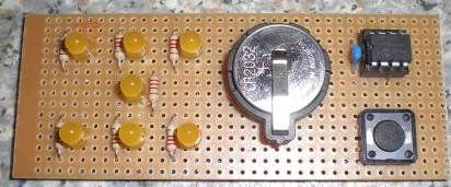
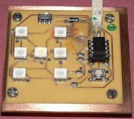
The
PIC Dice project constructed on Matrix Board.
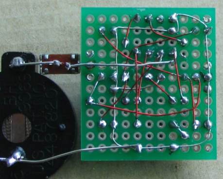
The underside of the board showing the
"point-to-point" wiring.
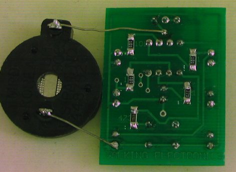
The topside of the Matrix Board and
the underside wiring
When the circuit is
switched on, the tactile switch is pressed and the LEDs flash to represent
the rolling of the dice.
The “rolling” gradually slows and a result appears on the LEDs. After 6
seconds the LEDs go out and the switch can be pressed again for another
“roll.”
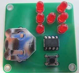
Here is the PIC DICE on Printed Circuit Board:
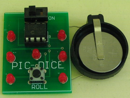
The negative of the cell holder goes to
the bottom rail

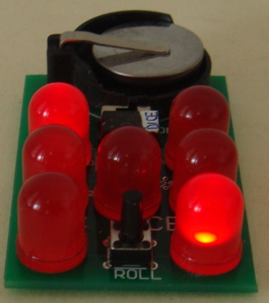
PIC LED Dice now comes with 10mm
Jumbo RED LEDs for $2.50 extra.
Ask for them when ordering.
The PC board is also larger.
|
PIC Dice
PARTS LIST
Kit: $8.50
plus $4.00 postage |
|
|
3 - 100R
surface mount
1 - 220R SM
1 - 47k SM
7 - 3mm high-bright red LEDs
1 - 8 pin IC socket
1 - PIC12F629 microcontroller with DICE
1 - tactile switch
1 - mini on-off slide switch
1 - coin cell holder
1 - 3v lithium coin cell CR2025
Fine tinned copper wire - 6cm
Fine solder – 20cm
1 - PIC DICE PC Board |
|
Here are the files you
will need to burn the program into the PIC12F629 micro:
Dice.asm
Dice.txt
Dice.hex
Dice_hex.txt
Dice.zip
;*************************************************************
;;PIC Dice.asm         *


;7 LEDs  - slow down and stops on a random face of a dice -


	list	p=12F629
	radix	dec
	include	"p12f629.inc"

	errorlevel -302	; Dont complain about BANK 1 Registers

	__CONFIG _MCLRE_OFF & _CP_OFF & _WDT_OFF & _INTRC_OSC_NOCLKOUT

	; globals
	;20h		;this is the first available file


fileA	equ		26h
fileB	equ		27h
fileC	equ		28h
fileD	equ		29h
temp1	equ		2Ah
temp2	equ		2Bh
temp3	equ		2Ch

random	equ		30h


	;5Fh		;this is the last available file

status		equ	03h
option_reg	equ 	81h


	; bits on GPIO

pin7		equ	0	;GP0
pin6	 	equ	1	;GP1
pin5		equ	2	;GP2
pin4		equ	3	;GP3 input only
pin3		equ	4	;GP4
pin2		equ	5	;GP5


	;bits

rp0	equ	5	;bit 5 of the status register


Start	org	0x00	;program starts at location 000
	nop
	nop
	nop
	nop		;NOPs to get past reset vector address
	nop
	nop


SetUp	bsf	status, rp0 	;Bank 1
	movlw   b'11001000' 	;GP3 input
 	movwf   TRISIO
        bcf	status, rp0	;bank 0
	movlw   07h     	;Set up W to turn off Comparator ports
        movwf   CMCON       	;must be placed in bank 0
        clrf 	GPIO       	;Clear GPIO of junk
	clrf	random
	goto 	Main


	;Delay  - slow-down
        ;This is where the random number is generated. The micro very
        ;quickly comes to Del_1 while the switch is still pressed and
        ;increases Random very quickly until the switch is released.

Del_1	movlw 	01h
	movwf 	fileC
	movf	temp1,0
	movwf	fileB
DelY	decfsz 	fileA,1
	goto 	DelY
	btfsc	GPIO,3
	goto	_AA
	incf	random,1
	movlw	07
	subwf	random,0
	btfss	03,0	    ;test the Carry.
	goto	_AA         ;Carry is SET if W is less than or equal
	clrf	random
	incf	random,1
_AA	decfsz 	fileB,1
	goto 	DelY
	decfsz 	fileC,1
	goto 	DelY
	retlw 	00

	;This is the final display-delay before going blank

Del_10	movlw 	12h
	movwf 	fileC
DelZ	decfsz 	fileA,1
	goto 	DelZ
	decfsz 	fileB,1
	goto 	DelZ
	decfsz 	fileC,1
	goto 	DelZ


	;This is where the program blanks the display and makes the
        ;inputs/outputs into inputs to reduce the
        ;current during SLEEP

blank	bsf	status, rp0 	;Bank 1
       	movlw	b'11111111'	;Set GP 1,2 4 5 input
	movwf	TRISIO	   	;
	movf	GPIO,0
	movlw	b'00001000' 	;must clear the GPIF flag!!
	movwf	INTCON
	bsf	IOC,3
	sleep
	nop
	bcf	status, rp0	;bank 0
	goto	SetUp


cycle	movlw 	0Ch
	movwf	temp3
	movlw	20h
	movwf	temp2
cycle1	call 	face1
	incf	temp2,1
	incf	temp2,1
	incf	temp2,1
	movf	temp2,0
	movwf	temp1
	call 	Del_1

	call 	face2
	incf	temp2,1
	incf	temp2,1
	incf	temp2,1
	movf	temp2,0
	movwf	temp1
	call 	Del_1

	call 	face3
	incf	temp2,1
	incf	temp2,1
	incf	temp2,1
	movf	temp2,0
	movwf	temp1
	call 	Del_1

	call 	face4
	incf	temp2,1
	incf	temp2,1
	incf	temp2,1
	movf	temp2,0
	movwf	temp1
	call 	Del_1

	call 	face5
	incf	temp2,1
	incf	temp2,1
	incf	temp2,1
	movf	temp2,0
	movwf	temp1
	call 	Del_1

	call 	face6
	incf	temp2,1
	incf	temp2,1
	incf	temp2,1
	movf	temp2,0
	movwf	temp1
	call 	Del_1
	decfsz	temp3,1
	goto 	cycle1
	retlw	00


end1	call 	face1
	movf	temp2,0
	movwf	temp1
	call 	Del_1
	retlw	00

end2	call 	face2
	movf	temp2,0
	movwf	temp1
	call 	Del_1
	retlw	00


end3	call 	face3
	movf	temp2,0
	movwf	temp1
	call 	Del_1
	retlw	00

end4	call 	face4
	movf	temp2,0
	movwf	temp1
	call 	Del_1
	retlw	00


end5	call 	face5
	movf	temp2,0
	movwf	temp1
	call 	Del_1
	retlw	00


face1	movlw	b'00010000'		;
	movwf	GPIO
	retlw 	00


face2	movlw	b'00000100'		;
	movwf	GPIO
	retlw 	00


face3	movlw	b'00010100'		;
	movwf	GPIO
	retlw 	00


face4	movlw	b'00000110'		;
	movwf	GPIO
	retlw 	00


face5	movlw	b'00010110'		;
	movwf	GPIO
	retlw 	00


face6	movlw	b'00100110'		;
	movwf	GPIO
	retlw 	00


finish1	call	end1
	goto	Del_10

finish2	call	end1
	call	end2
	goto	Del_10

finish3	call	end1
	call	end2
	call	end3
	goto	Del_10

finish4	call	end1
	call	end2
	call	end3
	call	end4
	goto	Del_10

finish5	call	end1
	call	end2
	call	end3
	call	end4
	call	end5
	goto	Del_10


       ;This is where the Random number is decremented to produce the
       ;final value on the display

Main	btfsc	GPIO,3
	goto	Main
	call	cycle
Main1	decfsz	random,1
	goto	Main2
	goto	finish1
Main2	decfsz	random,1
	goto	Main3
	goto	finish2
Main3	decfsz	random,1
	goto	Main4
	goto	finish3
Main4	decfsz	random,1
	goto	Main5
	goto	finish4
Main5	decfsz	random,1
	goto	Del_10
	goto	finish5


end |
ooo00000ooooooxx
12-9-2014
|