This discussion explains the instructions for the PIC12F629 and PIC16F628.
(most of this discussion has been taken from PCB Heaven but the English has been corrected plus many mistakes have been corrected).
The PIC chips we are using have just 35 instructions to carry out all the features of the chip. All instructions have the same format. First is the name of the instruction, such as movlw for "move" or btfss for "bit test." Then the instruction itself. It can define a register (f), such as movwf test1 where test1 is register 22h or a bit (b), such as btfss test1,2 a literal, (a literal is another word for a "number," such as movlw d35 where 35 is put into the "working register" of the micro. The number can also be called a "constant" or a "piece of data." Or the instruction can define a place to go to in a program. This place will be identified by a "label" such as goto testB. Or the instruction can have a destination (d), such as goto $+4 where the $ symbol identifies the present address and +4 tells the micro to advance 4 instructions down the program. The instruction $-6 tells the micro to go UP the program 6 instructions.
File Address (f).
A file is also known as a Register. All PICs have a number of files or registers that can be used during the execution of a program to hold pieces of data. The files for the PICs we are using start at 20h to 5Fh for the PIC12F629 and 20h to 7Fh (plus 128 extra) for the PIC16F628. A file address is a field that indicates the absolute position of a register within the RAM. This field could be filled with either a number (e.g. 0x05h for PortA or 0x06h for PortB). Files start at 20h.
You can work with a file by using its address, such as 20h via an instruction such as movf 20h,0 or btfss 20h,1 or decfsz 20h,1
Or you can define each file you will using in your program, at the start. Such as:
green equ 20h
DTMF equ 21h
test1 equ 22h
You then produce instructions such as: movf green,0 or btfss green,1 or decfsz green,1 and the compiler will associate green with file 20h during the conversion of your .asm (your hand-produced program in NotePad) to .hex file that will be used to "burn" (program) the chip.
Bit Address (b)
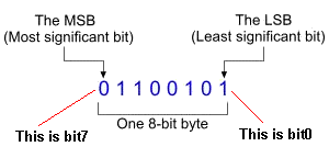
Each byte is composed of bits. For the 8-bit PICs, each byte is composed of 8 bits. When a field requires a bit address, it means a number from 0 to 7 must be placed in the instruction. 0 corresponds to the Least Significant Bit (LSB) and it is the most right placed bit within the byte. 7 corresponds to the Most Significant Bit (MSB) and it is the most left placed bit within the byte.
Literal, constant, data or label (k)
This field is generally a number. This number may be from a previous-defined constant, or piece of data, or from a label within the code. When we talk about a literal we mean a number. This is generally between 00 and 255. A constant is also a number. A piece of data is also a number. A label is generally the name of a sub-routine and identifies the start of the sub-routine.
Destination (d)
After an instruction is executed, the result can be placed in the original file or it can be placed in W (the working Register) and the original file will not be altered.
The destination can be either 0
or 1, where 0 represents the Working register and 1 represents the file. It is used in instructions that will return a byte as a result
of an operation. The destination field will define where this byte will
be stored. If this field is 0, the byte will be stored in the
working register (W). If the destination is 1, the byte will be
stored in the register where the operation was performed. You can
also write 'w' for 0 or 'f' for the file.
Typical examples to show the destination of the result of an operation:
movf green,0
The value stored in green will be copied to the working register.
movf green,1
The value stored in green will be taken out and then moved back to the
green file.
The zero flag in the Status file will be SET if the file is EMPTY.
decfsz green,1 The green file
will be decremented and the result will be placed in the file.
The micro will jump over the next instruction if the file is EMPTY.
There is no direct way to place a
number directly into a file. It must first be loaded into w
(using the movlw instruction: movlw d55) then moved to the file
using movlw, such as movwf green.
8-bit PIC microcontrollers can load binary values up
to 8-bits. If you try to load values larger than 8-bits, only the
first 8 bits will be loaded and the rest will be omitted.
- b'10101010'
The 'b' tells the compiler that a binary number follows. The quotes are necessary. Just like the decimal human-orientated base, if a binary number needs less than 8-bits to be represented, all zeros on the left side of the number can be omitted. For example, these two are the same:
- b'00011110'
- b'11110'
Decimal
The decimal base is human-orientated. It is easier to understand 255 than b'11111111'.
- d'255'
The letter 'd' before the number tells the compiler that a decimal number follows. The quotes are necessary.
This is another useful base that you may need to know. It is most useful because number representations such as memory positions use this base. To represent a hexadecimal number, you use the follow form:
- 0xa2
Unlike before, the value does not require a letter before the number. Instead, 0x is used and no quotes enclose the number. The 8-bit system can handle hexadecimal numbers up to 0x0ff. Larger numbers will act as previously mentioned.
| Instruction | Description |
| movlw k | Loads a literal value 'k' into the W register movlw b'11011010' ;A binary value is loaded into the W register movlw d'218' ;The value in decimal base is loaded into the W register movlw 0xda ;The value in hex base is loaded into the W register |
| movwf | Moves the value from the W register to the
file register 'f' This example requires you to declare a file register, for example: TempReg equ 0x20 movlw d'80' ;the W register has the decimal value '80' movwf TempReg ;the TempReg register now has the value '80' |
| movf green,d | Loads a value from "green" to W or back into "green." If d is 0 the result is stored in the W register, if d is 1 the result is stored back in "green." The zero flag (in the Status file) is affected. If "green" is empty and the instruction: movf green,f is performed, the zero flag will be SET. |
Flow Instructions
These instructions affect the normal flow of the program. Usually, the program flows line by line. This means that when an instruction on line 10 is executed, the next instruction will be executed. But some instructions change the flow. A GOTO for example may send the program from line 10 to line 100.
| Instruction | Description |
| goto k | Send the micro to another instruction or label. When the program flow reaches a GOTO instruction, it goes to the program line or label placed in the k field. The k field can be from 0 to 2047. The micro does not remember the address where the GOTO instruction was located and thus the program cannot "return." Use "call" if you want to return to the original place of the "branch." To GOTO a program line, you need to place a LABEL at the location such as "tone1" and use the instruction: goto tone1 or you can use: goto $+45 |
| call k | Send program flow directly to a program line
or label. The address of the CALL instruction is pushed onto the
stack. A RETURN instruction will send the program flow back to
the address
where the CALL was made. The micros we are using have an "8-Stack" and this means you can have up to 8 CALLS. You cannot end a sub-routine with a CALL. The next line after a call must be "retlw 00" so the micro eventually gets back to the original address. |
| retlw k | This instruction will send the program flow to the last position pushed onto the stack, due to a CALL instruction. Also, the W register will return with the value k (00 to ff). |
| retfie | This is a RETurn From Interrupt instruction. This instruction will send the program flow back to the position where the last interrupt occurred and caused the program flow to go to the interrupt vector (0x04h). It will set the GIE bit (Global Interrupt Enable) of the INTCON (INTerrupt CONtrol) register and will re-enable all interrupts. |
Mathematical Instructions
| Instruction | Description |
| addlw k | Add the content of W register with a literal
value and store the result in the W register.
The status that may be affected from
this instruction are:
|
| addwf file,d | Add the content of W register with the
contents of a file. If d is 0 the result is stored in the W
register, if d is 1 the result is stored back to the file.
The status that may be
affected from this instruction are:
|
| sublw k | Subtract the contents of W register from a
literal value and store the result in the W register.
The status that may be
affected from this instruction are:
|
| subwf file,d | Subtract the contents of W register from a
file. If d is 0 the result is stored in the W register, if d is
1 the result is stored back to the file register 'f'.
The status that may be
affected from this instruction are:
movlw d'100' ;The W register has the value '100' movwf TempReg ;The TempReg has now the value '100' movlw d'30' ;The W register has the value '30' subwf TempReg,1 ;The value of W is subtracted from TempReg ;and the result (70) is stored back in TempReg |
| comf file,d | The contents of the file
complemented. If d is 0 the result is stored in the W register,
if d is 1 the result is stored back to the file register 'f'.
TempReg equ 0x20 movlw b'11000101' ;The W register has the value '11000101' movwf TempReg ;The TempReg has now the value '11000101' comf TempReg,1 ;The values of TempReg is complimented and the result (00111010) is stored to TempReg |
| Instruction | Description |
| andlw k | Logic AND between the contents of W and the
literal value k. The results is stored back into W. movlw b'10000100' ;the W register now has the binary value '10000100' andlw d'00001111' ;the binary value '00000011' is ANDed with the W register. ;the W register has the binary value '00000100' |
| andwf file,d | Logic AND between the content of W register
with the content of a file register 'f'. If d is 0 the result is
stored in the W register, if d is 1 the result is stored back to
the file register 'f'. movlw b'10000100' ;W register has the value '10000100' movwf TempReg ;TempReg now has the value '10000100' movlw d'00001111' ; W register has the value '00001111' andwf TempReg,1 ; W register ANDed with the contents of TempReg. The result ('00000100') ;is stored in TempReg |
| iorlw k | Logic OR between the contents of W and the
literal value k. The results is stored back to W. movlw b'10000100' ;W register now has the binary value '10000100' iorlw d'00001111' ;the binary value '00000011' is ORed with the W register. ;the W register has the binary value '10001111' |
| iorwf file,d | Logic OR between the content of W register
from the content of a file. If d is 0 the result is stored in
the W register, if d is 1 the result is stored back to the file. movlw b'10000100' ;W register has the value '10000100' movwf TempReg ;TempReg now has the value '10000100' movlw d'00001111' ;W register has the value '00001111' iorwf TempReg,1 ;W register ORed with the contents of TempReg ;and the result ('10001111') is stored to TempReg |
| xorlw k | Logic EXCLUSIVE OR between the contents of W
and the literal value k. The results is stored back to W. movlw b'10000100' ;W register has now the binary value '10000100' xorlw d'00001111' ;binary value '00000011' XORed with the W register. ;the W register has the binary value '10001011' |
| xorwf file,d | Logic EXCLUSIVE OR between the content of W
register from the content of a file register 'f'. If d is 0 the
result is stored in the W register, if d is 1 the result is
stored back to the file register 'f'. movlw b'10000100' ;W register has the value '10000100' movwf TempReg ;TempReg now has the value '10000100' movlw d'00001111' ;W register has the value '00001111' xorwf TempReg,1 ;W register ORed with the contents of TempReg ;and the result ('10001011') is stored to TempReg |
Logic Functions Table
The following table shows the result of the above functions between two bits.
| Bit 1 | Bit 2 | AND | OR | XOR |
| 0 | 0 | 0 | 0 | 0 |
| 0 | 1 | 0 | 1 | 1 |
| 1 | 0 | 0 | 1 | 1 |
| 1 | 1 | 1 | 1 | 0 |
| Instruction | Description |
| bsf file,b | The bit 'b' in the file is Set (1).
The right hand bit is bit0 and the left-hand bit is bit7. bsf portA,0 ;The bit in position 0 in 'portA' is SET (1). |
| bcf file,b | The bit 'b' in the file is Cleared
(0). bcf portB,0 ;The bit in position 0 in 'portB' is CLEARED (0). |
| btfss file,b | If the bit 'b' in the file is 1, the micro
jumps over an instruction and executes the next. If the bit is
0, the instruction is executed normally. btfss portA,4 ;Check bit '4' in register portA micro goes here if bit 4 is 0 micro goes here if bit 4 is 1 |
| btfsc file,b | If the bit 'b' in the file is 0,
the micro jumps over the following instruction and executes the
next instruction. If the bit is 1, the instruction is executed
normally. |
| swapf file,d | The upper and lower nibbles of the file are
exchanged. If d is 0 the result is stored in the W register, if
d is 1 the result is stored back to the file. movlw b'11110000' ;W has the binary number '11110000' movwf TempReg ;TempReg has the binary number '11110000' swapf TempReg,1 ;The nibbles in TempReg are swapped ;Now TempReg has the value '00001111' |
Byte Orientated Instructions
The byte orientated instructions are instructions to alter a complete byte of a file:
| Instruction | Description |
| rlf file,d | Rotate Left through carry. This instruction will shift all bits of
the file one
position left. The MSB bit will be sent to the Carry, and the Carry bit
will be sent back to the register's LSB. If d is 0 the result is stored in the W
register, if d is 1 the result is stored back to the file.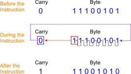 |
| rrf file,d | Rotate Right through carry.
This instruction will shift all bits of
the file one
position right. The LSB bit will be sent to the Carry, and the Carry bit
will be sent back to the register's MSB. If d is 0 the result is stored
in the W register, if d is 1 the result is stored back to the
file.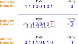 |
| incf file,d | The contents of the file are increased by 1. If d is 0
the result is stored in the W register, if d is 1 the result is
stored back to the file. |
| decf file,d | The contents of the file are decreased by 1. If d is 0
the result is stored in the W register, if d is 1 the result is
stored back to the file. |
| incfsz file,d | The contents of the file are increased by 1. If d is 0
the result is stored in the W register, if d is 1 the result is
stored back to the file. If the result is '0', the next instruction
is jumped over and the following instruction is executed. The layout of instructions are as follows: incfsz fileC,1 goto $-1 goto show The micro will execute incfsz fileC,1 and move to goto $-1 then go to incfsz fileC,1 and increment to goto $-1 etc etc etc. But when fileC contains "ff" the next increment will make it "00" and the micro will jump to goto show. |
| decfsz file,d |
The contents of the file are decreased by 1. If d is 0
the result is stored in the W register, if d is 1 the result is
stored back to the file. If the result is '0', the next instruction
is jumped over and the following instruction is executed. The layout of instructions are as follows: incfsz fileC,1 goto $-1 goto show The micro will execute incfsz fileC,1 and move to goto $-1 then go to incfsz fileC,1 and increment to goto $-1 etc etc etc. But when fileC contains "ff" the next increment will make it "00" and the micro will jump to goto show. |
| clrf file | The file is cleared.
The Zero Status is always SET:
|
| clrw | The working register W is cleared.
The Zero Status is always SET:
|
Miscellaneous Instructions
| Instruction | Description |
| nop |
This is the No Operation instructions. When this is executed,
nothing will happen at all. It has no occurrence to anything on
the chip or program. This instructions is commonly used to
create time delays. nop ;This program will do nothing at all nop nop |
| clrwdt |
This instructions will clear the Watchdog timer. The Watchdog
timer is a very useful independent on-chip timer that is used to
ensure the chip is operating normally. When the Watchdog
timer is enabled, it will "time out" after a certain number of
microseconds. This corresponds to a certain number of
instructions. You must reset the watchdog timer before this
occurs by making sure it gets reset throughout your whole
program by counting the number of instructions between each
reset. This becomes very complex when you have delays nd you normally need to add a clrwdt within a delay. If the timer is not reset within its time period, it will reset the PIC and the program will start over, because it will assume the program flow is interrupted or fallen into an infinitude loop. |
| sleep |
This instruction will put the chip into Sleep
mode. Sleep mode is a state where the PIC will draw as low as
0.1uA and it will only have some basic operations still running
for waking it up. The Sleep mode is basically for power
maintenance. |
The Status Register
The Status register contains the arithmetic status of the Arithmetic Logic Unit, the Reset status of the PIC and the Bank Selection bits, direct and indirect. The bits of the Status register as as follows:
| Bit # | 7 | 6 | 5 | 4 | 3 | 2 | 1 | 0 |
| Access | R/W | R/W | R/W | R | R | R/W | R/W | R/W |
| Initial | 0 | 0 | 0 | 1 | 1 | x | x | x |
| Name | IRP | RP1 | RP0 | -TO | -PD | Z | DC | C |
Bit 0 - C: Carry/-Borrow
- 0: No carry-out from the MSB of the result occurred
- 1: A carry-out from the MSB of the result occurred
This bit is Readable and Writable and after a reset it's value will be unknown. If an instruction executed has an effect on this bit, then this bit becomes automatically and temporarily Read Only. The Carry bit watches if a carry-out from the MSB bit occurs. The values it can get are:
Bit 1 - DC: Digit Carry/-Borrow
- 0: No carry-out from 4th lower order of the byte occurred
- 1: A carry-out from the 4th lower order of the byte occurred
This bit is Readable and Writable and after a reset it's value will be unknown. If an instruction executed has an effect on this bit, then this bit becomes automatically and temporarily Read Only. The Digit Carry bit watches if a carry out from the 4th lower order of the byte is occurred. The values it can get are:
Bit 2 - Z: Zero
- 0: The result of an arithmetic or logic operation was not zero
- 1: The result of an arithmetic or logic operation was zero
This bit is Readable and Writable and after a reset it's value will be unknown. If an instruction executed has an effect on this bit, then this bit becomes automatically and temporarily Read Only. The Zero bit watches if the result of an arithmetic or logic operation was zero. The values it can get are:
Bit 3 - -PD: Power Down
- 0: The 'SLEEP' instruction was executed
- 1: Power Up or the 'CLRWDT' instruction was executed
This bit is Read Only and after a reset it will get the value 1. The Power Down bit watches if the 'SLEEP' instruction was executed. The values it can get are:
Bit 4 - -TO: Time Out
- 0: A Watchdog timer time out occurred
- 1: Power Up, 'SLEEP' or 'CLRWDT' instruction was executed
This bit is Read Only and after a reset it will get the value 1. The Power Down bit watches if a Watchdog timer time out occurred. The values it can get are:
Bit 6:5 - RP<1:0>: Register Bank Selection
- 00: Bank 0 is selected
- 01: Bank 1 is selected
- 10: Bank 2 is selected
- 11: Bank 3 is selected
Those bits are Readable and Writable and after a reset it will all get the value 0. Their task is to select the active Register Bank in use. The values it can get are:
Bit 7 - IRP: Register Bank Selection used with indirect addressing
- 0: Indirect addressing current bank selected is Bank 0 and Bank 1
- 1: Indirect addressing current bank selected is Bank 2 and Bank 3
During the indeterminate pages of this book, the indirect addressing shall be discussed and explained. The indirect addressing is a way of accessing registers (General Purpose or Special Function Registers) without directly accessing their memory position, but throughout an indirect addressing register. When this register is used, the current bank selected is different than the indirect current bank selected. The values it can get are:
The Option_Reg Register
The Option_Reg register is a Readable and Writable register that is used to control some modules of the PIC. The bits of the Option_Reg are as follows:
| Bit # | 7 | 6 | 5 | 4 | 3 | 2 | 1 | 0 |
| Access | R/W | R/W | R/W | R/W | R/W | R/W | R/W | R/W |
| Initial | 1 | 1 | 1 | 1 | 1 | 1 | 1 | 1 |
| Name | -RBPU | INTEDG | TOCS | TOSE | PSA | PS2 | PS1 | PS0 |
Bit <2:0> - PS<2:0>: Prescaler rate selection
Those bits are Readable and Writable and after a reset they will get the value '1'. They are used to set the Prescaler rate. The values it can get are:
| Bit value | TMR0 Rate | WDT Rate |
| 000 | 1:2 | 1:1 |
| 001 | 1:4 | 1:2 |
| 010 | 1:8 | 1:4 |
| 011 | 1:16 | 1:8 |
| 100 | 1:32 | 1:16 |
| 101 | 1:64 | 1:32 |
| 110 | 1:128 | 1:64 |
| 111 | 1:256 | 1:128 |
Bit 3 - PSA: Prescaler Assignment
- 0: The prescaler is assigned to the Timer 0 module (TMR0)
- 1: The prescaler is assigned to the Watchdog timer (WDT)
This bit is Readable and Writable and after a reset it will get the value 1. This bit is used to assign the prescaler to to the Watchdog timer or the Timer 0 module. The values it can get are:
Bit 4 - TOSE: Timer 0 Source Edge Select
- 0: Increment on Low to High
- 1: Increment on High to Low
This bit is Readable and Writable and after a reset it will get the value 1. It is used to select the RA4/TOCKI pin clock edge (High to Low or Low to High) on which the Timer 0 will count. The values it can get are:
Bit 5 - T0CS: Timer 0 Clock Source Select
- 0: Timer 0 clock source is the Internal instruction cycle clock (CLKO)
- 1: Timer 0 clock source is the RA4/TOCKI pin
This bit is Readable and Writable and after a reset it will get the value 1. This bit will define the Timer 0 module clock source. It can be either the RA4/TOCKI pin or the Internal Instruction Cycle Clock (CLKO). The values it can get are:
Bit 6 - INTEDG: RB0/INT pin Interrupt Edge Select
- 0: The RB0/INT interrupt will occur on the falling edge of the RB0/INT pin
- 1: The RB0/INT interrupt will occur on the rising edge of the RB0/INT pin
This bit is Readable and Writable and after a reset it will get the value 1. By altering this bit, you can select the RB0/INT pin pulse edge that the RB0/INT interrupt will occur. The values it can get are:
Bit 7 - -RBPU: PORTB Pull-up Enable
- 0: The RB pull-up resistors are enabled
- 1: The RB pull-up resistors are disabled
This bit is Readable and Writable and after a reset it will get the value 1. The RB ports have an internal programmable pull-up resistor to minimize the use of external pull-up resistors when needed. This bit will enable or disable those resistors. The values it can get are:
The TRIS and PORT registers
The PIC12F629 has 8 pins with 5 I/O pins and one input-only pin.
The PIC16F628 has 18 pins with 15 I/O pins one input-only pin.
These pins are called PORT PINS.
The pins of the PIC12F629 are called General Purpose In Out pins -
abbreviated to GPIO.
And the pins of the PIC16F628 are separated into two sets of 8 pins,
called portA and portB.
Each pin can be changed to an input or an output at any time during the
running of a program and this is done by a file called TRIS. The name of
the file for the PIC12F629 is called TRISIO and for the PIC16F628, it is
called TRISA and TRISB.
When a bit in the TRIS register is "1" the corresponding bit in the
in/out file becomes an INPUT. When a bit in the TRIS file is "0" the
corresponding bit in the in/out file becomes an OUTPUT.
When a bit in the TRISIO register is "1" the corresponding bit in the
in/out file (this is called GPIO) becomes an INPUT. When a bit in the
TRISIO file is "0" the corresponding bit in the in/out file (this is
called GPIO) becomes an OUTPUT.
For the PIC12F629 the TRIS file is called TRISIO and only the 6 lower bits are used.
The TRISIO file is in bank1 (most of the other files are in bank0). To get to bank1, the following instructions are needed:
| bsf | status, rpo | ;Bank1 | |
| movlw | b'xx000000' | ;(however GP3 is input-only and will not become an output) | |
| movwf | trisio | ;Write to TRISIO register | |
| bcf | status, rpo | ;Bank0 |
CONFIGURING GPIO
GPIO is the actual port (consisting of 6 lines) in a PIC12F629, that
drive LEDs (up to 25mA per line) or can be configured as inputs.
If the lines have been configured as outputs, via TRISIO, they can now
be made either HIGH or LOW by defining the bits in GPIO, thus:
movlw b'xx110000'
movwf gpio
(however GP3 is input-only and will not become an output)
CONFIGURING TRISA
The PIC16F628 has 2 ports, PORTA and PORTB.
Suppose you
set TRISA to: b'11111111' PORTA will be all
inputs.
And if you set TRISA to: b'00000000' PORTA will be all
outputs.
The TRISA file is in bank1 (most of the other files are in bank0).
To get to bank1, the following instructions are needed:
| bsf | status, rpo | ;Bank1 | |
| movlw | b'00000000' | ;PORTA will be all outputs. (however RA5 is input only and will not become an output) | |
| movwf | trisA | ;Write to TRISA register | |
| bcf | status, rpo | ;Bank0 |
CONFIGURING PORTA
You can now make each line of PORTA either HIGH or LOW by defining
the bits, thus:
movlw b'11110000'
movwf portA
The 4 lower outputs will be LOW and the 4 upper lines will be HIGH.
(however RA5 is input only and will not go HIGH).