|
Rock
Paper
Scissors
The game of Rock, Paper,
Scissors . . . using
a micro.
Page 1 Page 2

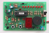
This
program has
been written for PIC LAB-1
and requires no extra components.
The files are in:
RPS files |
 |
|
|
The game
of Rock, Paper, Scissors has always fascinated me.
It's so simple.
The clever part is the rotary nature of the output.
Rock breaks scissors, Paper covers Rock and Scissors cuts Paper.
The first in each result always wins.
There are over 100 websites devoted to this game.
It has quite a cult following.
Some of the websites have an animated representation of the action of the
game.
If you don't know how to play it, HERE
is a FLASH demonstration and HERE
is another version you can play as an opponent.
There are also long-page-articles on the subject.
We cannot produce
anything like the complexity of the internet presentations as we are working with
one of the simplest microcontrollers, however we can show how to put a program
together to produce almost any effect on a row of LEDs and 7-segment
display.
The RPS program does not contain any strategy or "thinking" but it
can be designed for effect.
The three letters on the 7-segment show "R P S" to indicate
Rock, Paper, Scissors. This is the simple part. The lead-up to this involves flashing
the 8 LEDs.
There are 3 different sections of the program:
1. The 8-LED display
2. The random number generator
3. The overall sequencing of the program.
The 8 LED display can produce a number of effects such as "running,"
"flashing" or "splitting" and the 7-segment display can
produce almost all the letters of the alphabet.
The results on the screen need to be random and this can be achieved by a
random number generator, a table or by human intervention.
We will be making the program run automatically and thus a random number produced by
human intervention will not be possible.
As you will see in a moment, computers are not capable of producing truly
random numbers and so the solution is to have a long list of numbers in a table and the
micro increments down the list.
The overall sequencing of the program is a TIMING issue. Its just a matter of
producing a suitable delay for each effect and running through it at the right
speed.
RANDOM NUMBERS
Computers are not very good at producing random numbers.
There is nothing in a microcontroller that can be used to produce an unknown
number ON A REGULAR BASIS.
If the program is allowed to run automatically, it would be difficult to
generate a random number by looking at the contents of a set of files, for
example. You have no guarantee of getting an "even spread of
results".
On the other hand, if you produce a table, the spread can be absolutely even or
a slight advantage can be introduced.
Even the smallest "odds" can reap an enormous reward.
Casinos are supposed to have a "house advantage" of only a few
percent, and on the roulette table it is about 3%.
Suppose this "advantage" is transferred to a "poker
machine". It simply means you will lose all your money for every 33
plays!
It's simple mathematics. There are times when you win, but this simply
increases the number of "plays" before you lose everything.
The longer you play, the more guarantee you have of losing EVERYTHING.
It's an absolute certainty.
Mathematic doesn't lie.
The table used in our RPS game is not "weighted" and theoretically
you should win exactly 50% of the time.
This is a good predictor of human behaviour.
Everyone thinks they can "beat the odds" and predict an event
with a result better than 50%.
This is incorrect. Humans are not as good as 50%. They average about 45%. That's
why the average winnings on a table is about 5%.
Take the RPS game. Play it 100 times and see the result. It's a perfect challenge
. . .
CHIPS
The complexity of this game would require at least 6 chips if using older-style
circuitry. The overall cost would be higher than a micro design and development
time would be substantially greater.
With our design, additional features can be added very easily and at very
little cost, whereas a project made with discrete components would require
complete re-designing.
There is really no comparison, however some readers still need convincing of
the enormous advantages of designing a project around a micro.
If you are still working your way through the routines, try reading them
exactly how the micro interprets them. They have been presented in a layout
called "linear," with very few jumps up and down the page. All the
files and values are visible so you can see exactly what
is going on. It's as clear as we can possibly make it.
Any programs you produce can be designed along similar lines. They don't have
to be "high technology." Go through the programs we have already
presented. They will help you get a program together much faster than doing it
all yourself.
THE SUB-ROUTINES
When writing a program, individual sub-routines are created in any order, as you think of them, and
placed in the program in alphabetical order. Only write the code when you
have the inspiration to create it.
For each sub-routine, a result must be generated and placed in a flag file or
in a file that is not used by any other sub-routine. Don't branch-off from a
sub-routine to another sub-routine. Go back to main and use the result from the
sub-routine or flag file.
If you need to do another calculation or produce another effect, write CALL
xxxx instruction in Main. Go to the sub-routine, carry out the instructions and
return to Main.
Each sub-routine must have a RETURN to Main.
If a sub-routine increments a file, you must be sure the file has been
incremented only once otherwise the result will be
incorrect.
These are the main requirements.
THE
PROGRAM
The first effect on the display is called the "attract" mode. This
draws the player to the game. In our version the "Attract Mode"
is similar to "Split," where the LEDs are removed from the middle
until all are removed. The action is then reversed.
Push button "A" to start the game.
The display will produce a random effect and then a letter on the screen.
The screen shows the letter for about 3 seconds and the cycle repeats.
Compare the choice you make (rock, paper, scissors) with the display and work
out the winner.
The program can be extended by allowing the button to be pressed one, two or
three times for rock, paper or scissors and this will be recorded. The display
will show the score after say 20 games.
Each sub-routine is very easy to follow. No complex instructions have
been used.
But a few clever ideas have been introduced, such as . . .
1. In the Attract sub-routine, to put FF into a file, it is cleared and
decremented.
2. In the Run sub-routine, the RRF and RLF instructions move a bit
across the display and back again. To detect when a bit has "fallen off the end of a
file,"
the carry bit is tested.
3. Before each letter appears on the screen, an effect, such as
"Flash," "Run," or "Toggle," appears on the 8
LEDs. Both the "effect" and one of the letters is determined by a
random number table. To prevent the effect coinciding with the letter on the screen, the jump value
for the effect is incremented twice in the Display sub-routine. To detect this
double-jump, the end of table needs two FF values.
4. To test for End of Table, bit 7 is tested. Any bit above bit 2 can be tested in
our case, we have used bit7 for convenience. There are three values in the
random number table. To test these three values, bits 0, 1 and 2 have been
used. This allows bit-testing. Bit0 = 0000 0001=1 , bit1 =
0000 0010=2 and bit 3 = 0000 0100=4. Bit testing is the easiest way to identify three values.
;RPS-1.asm
;Project: Rock Paper Scissors
List P = 16F84
#include <p16F84.inc>
__CONFIG 1Bh ;_CP_OFF & _PWRTE_ON
& _WDT_OFF & _RC_OSC |
SetUp
Table
Attract
Delay1
DelA
Del300
DelB
Del100
Del101
Display
Flash
Flash1
Run
RunA
Run1
Run2
Run3
Toggle
Toggle1
Main
MainA
MainB
Main2
Main3
Main4
MainC
MainD
Main5
Main6
|
ORG 0
BSF 03,5
MOVLW 03
MOVWF 05
CLRF 06
BCF 03,5
CLRF 1C
CLRF 1D
CLRF 1F
GOTO Main
ADDWF 02h,1
RETLW 04h
RETLW 01h
RETLW 02h
RETLW 02h
RETLW 04h
RETLW 04h
RETLW 02h
RETLW 01h
RETLW 02h
RETLW 01h
RETLW 04h
RETLW 02h
RETLW 04h
RETLW 02h
RETLW 01h
RETLW 04h
RETLW 04h
RETLW 01h
RETLW 01h
RETLW 04h
RETLW 02h
RETLW 01h
RETLW 02h
RETLW 01h
RETLW 04h
RETLW 02h
RETLW 04h
RETLW 02h
RETLW 02h
RETLW 01h
RETLW 04h
RETLW 02h
RETLW 04h
RETLW 02h
RETLW 01h
RETLW 04h
RETLW 04h
RETLW 01h
RETLW 01h
RETLW 04h
RETLW 02h
RETLW 01h
RETLW 0FFh
CLRF 06
DECF 06,1
CALL Del100
MOVLW 0E7h
MOVWF 06
CALL Del100
MOVLW 0C3h
MOVWF 06
CALL Del100
MOVLW 81h
MOVWF 06
CALL Del100
CLRF 06
CALL Del100
MOVLW 81
MOVWF 06
CALL Del100
MOVLW 0C3h
MOVWF 06
CALL Del100
MOVLW 0E7h
MOVWF 06
CALL Del100
CLRF 06
DECF 06,1
CALL Del100
CLRF 06
RETURN
MOVLW 0A
MOVWF 10h
CALL Del100
DECFSZ 10h,1
GOTO DelA
RETURN
MOVLW 03
MOVWF 10h
CALL Del100
DECFSZ 10h,1
GOTO DelB
RETURN
MOVLW 64h
MOVWF 1B
NOP
DECFSZ 1A,1
GOTO Del101
BTFSC 05,0
BSF 1F,0
DECFSZ 1B,1
GOTO Del101
RETURN
MOVF 0Eh,0
MOVWF 06
CALL Del100
CLRF 06
CALL Del100
MOVF 0Eh,0
MOVWF 06
CALL Del300
CLRF 06
CALL Del300
MOVF 0Eh,0
MOVWF 06
CALL Delay1
CALL Delay1
CALL Delay1
CALL Delay1
CLRF 06
CALL Delay1
INCF 1C,1
INCF 1D,1
RETURN
MOVLW 04
MOVWF 1E
CLRF 06
CALL Del100
CALL Del100
DECF 06,1
CALL Del100
CALL Del100
DECFSZ 1E,1
GOTO Flash1
CLRF 06
RETURN
MOVLW 04
MOVWF 1E
CLRF 06
INCF 06,1
RLF 06,1
BTFSC 03,0
GOTO Run2
CALL Del100
GOTO Run1
RRF 06,1
CALL Del100
RRF 06,1
BTFSS 03,0
GOTO Run3
DECFSZ 1E,1
GOTO RunA
CLRF 06
RETURN
MOVLW 04
MOVWF 1E
MOVLW 0F0h
MOVWF 06
CALL Del300
MOVLW 0Fh
MOVWF 06
CALL Del300
DECFSZ 1E,1
GOTO Toggle1
CLRF 06
RETURN
CALL Attract
BTFSS 1F,0
GOTO Main
MOVF 1C,0
CALL Table
MOVWF 11h
BTFSS 11h,7
GOTO MainB
CLRF 1Ch
GOTO MainA
BTFSS 11h,0
GOTO Main2
CALL Flash
GOTO Main4
BTFSS 11h,1
GOTO Main3
CALL Run
GOTO Main4
CALL Toggle
CALL Delay1
MOVF 1D,0
CALL Table
MOVWF 12h
BTFSS 12h,7
GOTO MainD
CLRF 1D
GOTO Main4
BTFSS 12h,0
GOTO Main5
MOVLW 33h
MOVWF 0E
CALL Display
GOTO MainA
BTFSS 12h,1
GOTO Main6
MOVLW 73h
MOVWF 0E
CALL Display
GOTO MainA
MOVLW 6Dh
MOVWF 0E
CALL Display
GOTO MainA
END
|
;Start of memory for the program.
;Go to Bank 1
>
;Load W with 0000 0011
;Make RA0, RA1 input
;Make all port B output
;Go to Bank 0 - the program memory area.
;Clear the jump counter
;Clear the jump counter
;Clear the button-press file
;Add W to Program Counter to create a jump.
;4
;1
;2
;2
;4
;1
;2
;1
;2
;1
;4
;2
;4
;2
;1
;4
;4
;1
;1
;4
;2
;1
;2
;1
;4
;2
;4
;2
;2
;1
;4
;2
;4
;2
;1
;4
;4
;1
;1
;4
;2
;1
;End of table
;"Attract"
Attract removes the LEDs from the
middle of ;the display and continues until all LEDs are removed,
then reverses.
;Clear the output
;Make the output file FFh. Illuminate all LEDs
;Call 100mS delay
;Remove the two centre LEDs
;Output the result
;Call 100mS delay
;Remove the 4 centre LEDs
;Output the result
;Call 100mS delay
;Remove the 6 centre LEDs
;Output the result
;Call 100mS delay
;Remove all the LEDs
;Call 100mS delay
;Display only the two outer LEDs
;Output the result
;Call 100mS delay
;Display the 4 outer LEDs
;Output the result
;Call 100mS delay
;Show all LEDs except the two centre LEDs
;Output the result
;Call 100mS delay
;Illuminate all LEDs
;Call 100mS delay
;Clear the display
;1 second delay
;100 loops = 100mS
;File 0E will have output value for 7-segment display
;Display the value
;Call 100mS delay to flash value on screen
;Clear display
;Call 100mS delay
;Show value again for 300mS
;Clear display
;Show value on screen for 4 seconds
;Clear screen
;Increment the jump-value for the "effect"
;Increment the RPS value
;"Flash" Flashes all 8 LEDs on the display 4 times.
;then RETURNs to Main
;Zero file 6 Turn off all LEDs
;Delay for 100mS
;Delay for 100mS
;Make file 06 = FF Turn on all LEDs
;Delay for 100mS
;Delay for 100mS
;Decrement the loop counter
;"Run" produces a Running LEDs effect across the
;display. The Running bit is stored in file 0D. It moves
;across and back 4 times
then RETURNs to Main
;Create "bit"
;Move the "bit" to the left
;Test the carry bit
;100mS delay
;Move the bit back onto the display
;100mS delay
;Move the "bit" to the right
;Test the carry bit
;Decrement the loop counter
;"Toggle" Flashes the top 4 LEDs then the bottom 4
;LEDs. This is repeated 4 times
;Create 4 loops
;Put 4 into loop counter
;Display top 4 LEDs
;Turn on 4 top LEDs
;Show for 300mS
;
;Turn on 4 bottom LEDs
;Show for 300mS
;Decrement the loop counter
;Clear the screen before leaving
;File 1C = jump value for
"Attract" sub-routine
before
;displaying RPS. File 1D = jump value for RPS value
;Copy 1C to W
;File 11h holds 1, 2, 4 or FF
;Test for End of Table
;End of table reached. Start at top
;See if effect is "Flash"
;See if effect is "Run"
;Effect is "Toggle."
;Call 1 second delay
;Copy 1D to W
;File 12h holds 1, 2 or 4
;Test for End of Table
;Produce "R"
;Put display value into file 0E
;Produce "P"
;Put display value into file 0E
;Produce "S"
;Put display value into file 0E
;Tells assembler end of program
|
|
GOING FURTHER
The program can be extended in many ways. On the next page we
will extend the program to include input from the player.
To Top
|