Plug-pack
Plug Packs can be found everywhere. They are strong and reliable and most
important, they are safe.
regulator
Turn an ordinary plug pack into a
regulated plug pack
![]()
They consist of a transformer enclosed in a plastic case with 2 or 3 pins at
one end that can be plugged directly into a power point. They come with all
sorts of equipment, from door bells to $2,000 plotters, but one disadvantage is
their size. Some are too big for the outlet, covering the other socket and
failing out of the wall at the slightest touch. The only way to use them is
plugged into a power board on the floor.
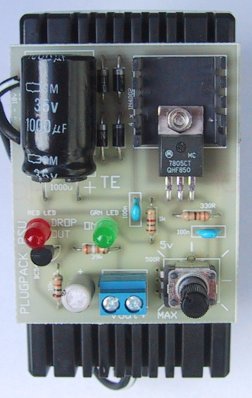
| The 1000u electrolytic bends over and lays against the board. The 2-screw terminal block is the output. |
|
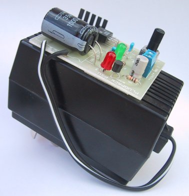
The board fitted to a plug pack with double-sided foam tape. The 500R pot adjusts the output voltage |
|
PLUG PACK REGULATOR CIRCUIT |
Some of the projects we have described in the past will operate quite successfully from a plug pack but because the output is so unreliable, we have been hesitant to recommend them.
If you connect an amplifier, radio or digital circuit to a plug pack, some packs have very poor smoothing and you can get hum from the amplifier or faulty operation from a digital circuit.
In addition, most plug packs deliver an output voltage that is considerably higher than that specified, when unloaded. The voltage given on the pack is its fully loaded value but when the current is low, the output voltage is much higher. As the current increases, the output voltage falls to the stated value.
For a 9v plug pack, the output can be as high as 12v to 13v on no load and a 12v plug pack can be 17v - 18v on no load.
This voltage is too high for some CMOS chips and far too high for TTL chips (TTL requires 4.5v - 5.5v), so plug packs have not been very popular with us to power many of our projects.
In comes the concept of REGULATION . . .
REGULATION
The voltage difference between no load and full load is called REGULATION and to put this quite simply, the transformers in plug packs are not very good. They are grossly over-rated and are the smallest size the manufacturer can get away with. Ideally, a transformer should drop a maximum of 10% from no load to full load - not 30%, but when they are over-rated, this is what happens.
When more current is drawn than the magnetic flux can supply, the voltage drops very quickly.
For instance, a 500mA plug pack is really only good for about 200-300mA and an 800mA pack is good for about 400-500mA.
But since most circuits draw peaks of current for short periods of time, the manufacturers have been able to over-rate plug packs to make them look impressive.
Very few users realise this and no one complains until something goes up in smoke.
Knowing this, we have designed a simple variable voltage power supply that will turn a very poor quality product into something worthwhile. And it has the advantage of having a transformer housed in a protective plastic case. This makes it ideal for beginners.
The output voltage and current of this project will depend on the rating of the plug pack and also the voltage setting of the pot. This may seem surprising, but the voltage of the output will determine the max current that can be drawn without overheating the regulator. The dissipation of the regulator is set by the size of the heat-sink and in our case the mini heat sink is capable of dissipating 3 watts for a reasonable temperature rise. Exactly how this comes about will be described in the next section.
HOW THE CIRCUIT WORKS
The plug pack regulator is an add-on for any Plug Pack. It will accept AC from 6v to 18v or DC from 9v to 18v and any current up to 1 amp.
The diode bridge on the input converts AC to DC and it doesn't matter which way around the leads are connected as the diodes compensate for either direction.
If a DC plug pack is used, the bridge can be left out and the leads taken directly to the positive and negative of the 1,000u electrolytic. If you use the bridge, no damage will result, however about 1.2v will be lost across it and this may reduce the output a little.
The 1,000u electrolytic is suitable for currents up to 500mA and if you want to use an 800mA or 1 amp plug pack, you will have to replace it with a 2,200u or add another 1,000u.
The circuit contains 2 indicator LEDs. The green LED is “POWER ON" and the red LED indicates "DROPOUT." This LED lets you know when you are drawing too much current or the output is shorted. It turns on when the output is less than 3v.
The other feature of this circuit is the variable output voltage. It can be adjusted from 5v to 9v (or 12v) and the board contains a simple scale around the 500R pot so that the pointer on the shaft will indicate the approximate voltage.
The regulator is a 7805 and this is a 5v type. The principle of operation of these 3-terminal devices is the output is always 5v higher than the "ground" lead. Click HERE for a discussion on the 3-terminal regulator.
If we "jack up" the ground lead, the output will rise also. This is how we get voltages higher than 5v.
But there is one thing that's most important. It's heat-sinking the regulator.
The heat generated by the regulator is a product of the voltage across it and the current flowing.
As an example, at 300mA and 12v out, the voltage across the regulator will be at least 3v (3v is the minimum across the regulator to prevent it dropping out of regulation), making the heat generated about 3 x 0.3 = 0.9 watts (900mW).
The heat-sink supplied in the kit is capable of dissipating 3 watts so we are below the maximum in this case.
But when the output is 5v and 300mA is flowing, the voltage across the regulator is 10v x 0.3A = 3 watts and the chip may start to heat up to a point where the thermal shut down feature will come into operation.
When this happens, the chip starts to oscillate at a very high frequency in an attempt to reduce the current and allow the temperature to fall.
This only occurs when the chip is very hot and to give you a warning before it starts to occur, we have included an OVERLOAD LED.
The overload circuit turns on when the output drops below 3v and this turns off a BC 547 transistor. This allows current to flow through the red LED. When the voltage rises again, the transistor turns on and the collector-emitter voltage is less than that required by the LED and it turns off.
In other words the transistor robs the LED of its 1.7v turn-on voltage.
The 100n capacitors must be mounted close to the leads of the regulator to prevent high frequency instability from occurring.
LM317
If you want the output voltage to be adjustable from 1.35v, you can replace the 7805 with an LM 317T 3-terminal regulator.
lt has a different pinout to the 7805 and all the leads must be bent
to fit down the holes in the PC board. The advantage of the LM317T is it is capable of going down to 1.35v.
It operates exactly the same as the 7805 in all
other respects.
|
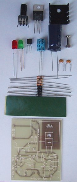
The Plug Pack Regulator kit |
|
PARTS LIST |
| 1 - 330R 1 - 1k 1 - 10k 1 - 39k 1 - 500R pot 2 - 100n monoblocks 1 - 100u 16v electrolytic 1 - 1000u 25v electrolytic 1 - 5mm red LED 1 - 5mm green LED 1 - 7805 3-terminal regulator 1 - BC 547 transistor 4 - 1N4002 diodes 1 - Mini U heat-sink 1 - Nut and bolt to suit 1 - Piece of double sided tape 1 - PLUG PACK PC BOARD |
|
Extras: |
| 1 - Plug Pack AC or DC output (100mA to 1 amp current rating) See text for more details. |
|
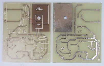
Plug Pack Regulator PCB |
CONSTRUCTION
All the parts fit on a small PC board with the regulator screwed to a mini heat fin and the 500R pot fits on top of the board
A scale is marked around the pot to correspond to a 12v plug pack and if you are using this type of pack, you have the output voltage ready-made.
If you are going to mount the project in a box, you can use a 500R mini trim pot as a pre-set and have no external adjustment available, or mount a 500R pot on the outside of the box and duplicate the scale.
Our suggestion is to fit the board onto the front face of a plug pack with a piece of double-sided foam tape. This makes the whole unit very compact.
Start assembly by fitting the leads of the regulator down its holes and screw it to the board with the mini "U" heat-fin between the regulator and the board. The metal side of the regulator must touch the heat fin so that any heat generated by the regulator will be passed to the atmosphere.
Next fit the 500R pot so that the three lead fit down the holes in the board as well as the two supporting tabs.
Next fit the 4 diodes so that they are touching the board, and solder them in position. Snip the leads close to the solder connection.
Next is the 1,000u electrolytic. Make sure the negative lead is near the edge of the board. Bend the electro over so that it lays onto the board. Solder the leads and the electro will stay in position.
Continue across the board with each component, noting that the two LEDs must be placed around the correct way. The cathode lead is the shorter one and the body of the LED has a flat next to the cathode.
The transistor fits over the "D" on the board and the 100u electrolytic has the negative lead near the edge.
A 2-screw terminal block is the output of the project and you can use the lead cut from the plug pack as a flying lead to the project you are powering.
CONNECTING THE TRANSFORMER
If you have a DC plug pack, you can leave the diodes out and connect to the top
and bottom holes of the bridge. If it is an AC plug pack, you must use the AC
input so that the bridge comes into operation.
An AC plug pack can be connected either way around but the lead on a DC supply
must be checked with a multimeter to determine the positive lead as the
striped lead is not always positive.
If the lead on the plug pack is long, you
can cut it short and use the excess as the output lead of the project;
otherwise you will need twin lead with the positive identified.
IF IT DOESN'T WORK
Very few things can go wrong with this project as it is very simple, but these
notes will help you with any possible faults.
The most dangerous thing that can happen to any voltage regulator circuit is
for the common lead to go "open." This will cause the output to rise to nearly
the same voltage as the input and can create a lot of problems.
Most circuits are very voltage sensitive and a rise in voltage can destroy the
IC's and transistors.
TTL chips cannot with-stand a voltage higher than 5.5v, CMOS chips have a
maximum of 18 - 22v and some audio chips will "shut down" when the voltage is
above 24v.
In our case, we have already seen that some plug packs produce an excessively
high voltage on no load and if a fault were to occur in the regulator section,
the project being supplied with the regulated voltage may be damaged.
The chance of a fault occurring is fairly remote but you can see that if the
common lead is not connected to the negative rail via the pot, the output will
rise without restraint.
This highlights the fact that the common lead must not be allowed to go high.
It will produce a
spike that may damage the circuit you are powering.
Another cause of high output voltage is an incorrect value for the pot. If it
is higher than 500R, you will not be able to get a smooth variation in voltage
and the scale will be one-ended.
If the output is below 5v, the first thing to do is feel the regulator. If it
is getting hot, a short circuit is present on the output. If it is not hot, the
input voltage may be too low or the regulator may be faulty.
If your plug pack is "AC," make sure you do not use the DC terminals as you
will damage the regulator.
The only other reason for a low output voltage, or one that will not rise above
5v, is a low input voltage. It must be at least 9v DC for a 5v out and higher
if you want to get more than 5v.
The loss across the bridge will be a minimum of 1.2v and the regulator will
drop about 3 - 4v.
There is one final point to be aware of when designing power supplies in the
future.
It is very easy to produce a supply with a current rating up to about 600 -
700mA as most of the low cost components such as transformers, diodes and
regulators are designed to handle 1 amp.
This is an absolute maximum value and if you want reliability you should limit
the project to 700mA.
Once you go over 700mA, you must go to the next range of components and use a 3
- 5 amp transformer, 3 amp diodes and a 5 amp regulator.
The cost jumps enormously and this will be a a topic for a project in the
future.