Point Controller
using
555 IC


Home

Cost: $15.00(incl servo) plus $6.50 postage
Kits are available

This projects converts a manual point into a remotely-controlled point using a servo. The switch in the kit controls the action and the servo in the kit does the work.

This project allows you to manually operate a point via a toggle switch.
Our project uses a SERVO, for the activation of the point and these have an output shaft that rotates nearly 300 degrees. But our project limits the rotation to about 90 degrees and this is enough to move the rails at the point via a rod called a "linkage."
An "arm" is fitted to the output of the servo to get linear motion via a short push-rod (from the arm to the rails).
The kit comes with the servo, switch and linkage to create a remotely controlled point at less cost than any other way.

LINKAGE
You need to connect the servo to the point with a stiff length of wire called a LINKAGE (also called a PUSH-ROD).
This allows the servo to produce LINEAR MOTION and the project reduces this linear motion to a very short distance to suit the "THROW" of the point. This is done by reducing the rotational movement of the servo via the circuit and using a hole close to the axel to produce just the right amount of "throw."
This is the distance the point must be moved to change the rail(s) from one position to the other.
Connection between the point and the servo is done with a short length of copper or steel wire included in the kit and this can be called a PUSH ROD, PULL ROD or LINKAGE.
It needs to be straight. It can be bent at the ends so it can be connected to the servo and lever on the track but the actual rod should be straight to deliver the "thrust."
You need to work out where to position the servo and then it can be housed in a signal-man's hut as shown in the photos.
The servo is laid on its side to take up the least room and held in position with double-sided tape.
When the servo has proven to be working correctly, it is glued to the baseboard with acetone cement around the edge of the servo.

THE CIRCUIT
The circuit is quite unconventional and it's the first time you will see such an usual design.
That's because we design unusual things.

The circuit delivers two different "timing values" to the 555 to produce clockwise and anticlockwise rotation. These values produce about 90° rotation and this is all you need to get the "throw" required.
The LEDs illuminate to show the direction of the point.
The project also includes a 2 metre extension lead so the servo can be located 2 metres from your control panel.
The project will work from a wide range of voltages, including AC or DC and as the voltage increases over 10v, the only effect will be the BC338 will get slightly warm if the point is constantly changed. The transistor will pass 800mA so it is easily capable of delivering the 250mA for the servo.
The single diode on the power supply produces half-wave rectification and although this does not produce very smooth DC, none of the circuit is very sensitive to noise. The first 100u provides a small amount of smoothing and the BC338 improves this enormously by only using the voltage from 0v to 6v2 and the ripple will be above this voltage. This is done by using a 6v2 zener on the base. The output is improved further by the second 100u to give the smooth voltage we need.
The 555 produces two different mark-space ratio arrangements at basically the same frequency of 20mS cycles. (50Hz)
The first diagram below is an animation and it shows a signal that is HIGH for 1mS, every 20mS, and it will rotate the arm fully clockwise. When the HIGH is about 2mS in width, (every 20mS), the arm will rotate to the fully anti-clockwise location. (The diagram is not in proportion - the base-line is actually 20mS long)

The animation below shows approximately the same thing:

By selecting a HIGH between the two extremes, the arm will rotate about 90°.

The 47k and 100k produce the timing (the HIGH) for the 555 to move the arm on the servo about  90°.
Either the 47k or the 100k is taken to the 5v6 rail via a PNP transistor and is turned ON to feed the 22n on the 555.
When the switch is changed to the other position, the other transistor operates the servo via the 555 in the other direction. 

THE KIT
The kit is cheaper than buying all the parts separately from local stockists and the LEDs are high bright because the current is only about 1 milliamp. The 90° header for the servo allows the 3-pin plug to be close to the board. There are a few components in the kit that are not readily available separately and that's why a kit is the best option.


ASSEMBLY
All the components fit on the board and the LEDs show the position of the point.
The toggle switch can be fitted to the board or mounted on your control panel.
The kit comes with a 2 metre extension lead (components) so the board can be positioned near the operator and the servo plugged into the 3-pin connector on the extension lead.


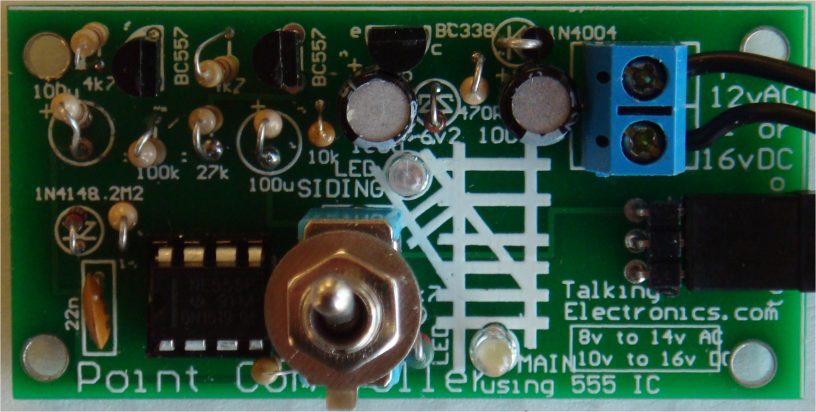
Close-up of the components on the PC board


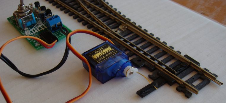
The output of the servo has the arm cut short so only one hole is available for the thick copper wire.
Bend the wire around the arm and use a hot soldering iron to melt the wire into the arm.
Keep the wire long so it provides a force to keep the moveable rail pressed against the outer track.


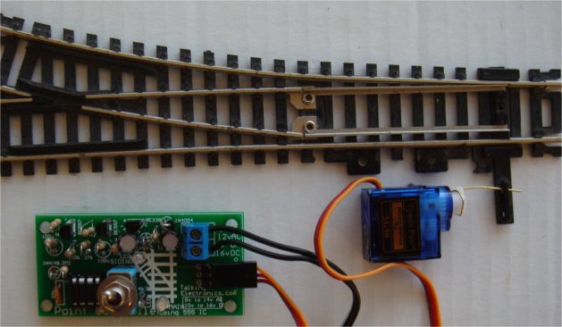
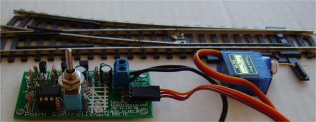
 BEFORE YOU START !!
Before you start thinking about buying the kit for this project, look at the range of POINT CONTROLLER projects from Talking Electronics and make sure this is the one you need.
The "point" needs to be a manually operated point. This projects does all the conversion.
It operates a single point and converts it to a remotely-operated point. It is the cheapest conversion you can get and uses a servo to do the work.
You can use AC or DC from about 10v to 14v (16v DC) and you can hide the servo in a hut or shed. The LEDs on the PC board show the condition of the track and the kit comes with a 2 metre extension lead. You just need a little bit of expertise to fit the "push-rod" (linkage) between the arm (on the servo) and the lever on the track that changes the position of the point. The photos will help you do this.    


Point Controller using 555 IC
Parts List

Cost:$15.00(incl servo) plus $6.50 postage
Kits are available
(Pre-assembled kits $5.00 extra)

1  - 470R   all 0.25watt
1  -  2k2
2  -  4k7
4  -  10k
1  -  47k
1  -  120k
1  -  2M2

1  -  22n ceramic
2  -  100u electrolytic

1  -  6v2 zener
1  -  1N4148 diode
1  -  1N4004 diode

1  -  3mm green LED (high bright)
1  -  3mm white LED (high bright)
1  -  BC338 transistor
2  -  BC557 transistors
1  -  555 IC
1  -  8 pin IC socket 

2m  -  3-core flat ribbon for servo extn lead

1  -  2-screw terminal block for power-in
1  -  3-pin 90° header for servo
1  -  3-pin male for servo extension lead
1  -  3-pin female socket for servo extension
1  -  20cm very fine solder 
1  -  Servo  with arms
1  -  Double-sided tape to temp hold servo
(glue needed to hold the servo in place)
1 - 10cm length thick copper wire for linkage
1  -  toggle switch SPDT
1  -  Point Controller using 555 IC PCB
 
Talking Electronics has many kits for Model Railways and each Kit has a different name so you know which kit to order. 

1/6/2017