|
Point Controller |
Talking Electronics has produced a number of Point Motor
Controllers, but this project uses a motor and gearbox to
control the points.
In other words it is a controller-circuit AND a POINT MOTOR - all for
$15.50
The kit contains a miniature motor / gearbox. This is a
miniature SERVO that needs to be modified by removing the
electronics and connecting two leads directly to the motor.
A DPDT push-switch is also included in the kit. This push-push
switch can be substituted for a toggle switch for $1.50 extra.
In other words this project is a controller-circuit AND a POINT MOTOR - all for
$15.50
All you have to do is connected the arm (commonly referred to as
a "horn"), on the output shaft of the servo, to a manual set of points and you can control them
remotely.
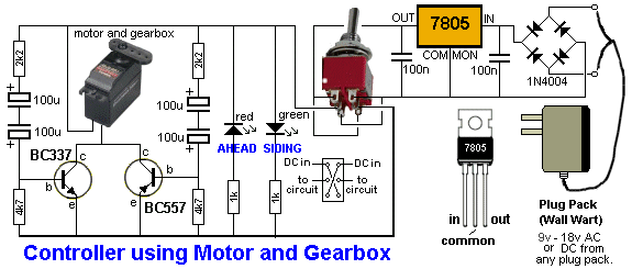
Each time the DPDT switch is changed, the voltage to the circuit
reverses and the opposite transistor conducts for a short period
of time while the electrolytics on the base charge. This
activates the motor to change the position of the points.
There is a small leakage through the transistors of about 20mA
at all times and that's why the project cannot be connected to a
battery.

It can be fitted in many different ways.
Laying it on its side will be the best option.
WHAT THIS PROJECT DOES:
The block diagram shows the project uses a Double-Pole
Double-Throw switch to reverses the voltage to a motor contained in a
servo, to change the position of the rails at a "point." The project
also has a timing feature to prevent the motor "jamming" and
burning-out.
The miniature motor and gearbox comes from a servo (commonly
called a servo motor) and all you have to do is remove the PC
board inside the case and connect two leads directly to the
motor.
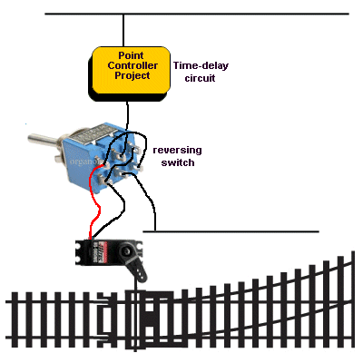
A Simplified block diagram of the
project
The gearbox delivers a very high torque to the output shaft
and we need to be careful not to supply full voltage to the
motor when it has reached its "limit-of-travel."
That's why the circuit reduces the current to the motor by the
time it reaches the "end-stop."
The transistors are designed to limit the current by the action of
the electrolytic charging via a resistor and slowly reducing
the current into the base.
When the supply is reversed via the switch, the initial current
is high and gradually tapers off when the arm reaches the limit
of its travel. This means the motor has very little torque by
the time it reaches the end and prevents "jamming."
The 4screw terminals on the PC board have been positioned so
each connector aligns with the 4 terminals on a DPDT
switch. Two criss-cross
wires are fitted to the switch to connect the other two terminals. This makes it easy to wire the switch. The kit comes
with a DPDT push-switch that you can change for a toggle switch.
The PC board also contains a red LED and green LED to let you know the
position of the points.
This is a very low-cost project for activating a set of points. 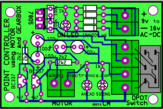
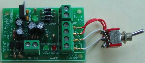
Point Controller project connects to Motor/Gearbox
(modified Servo)
The DPDT toggle switch is $1.50 extra
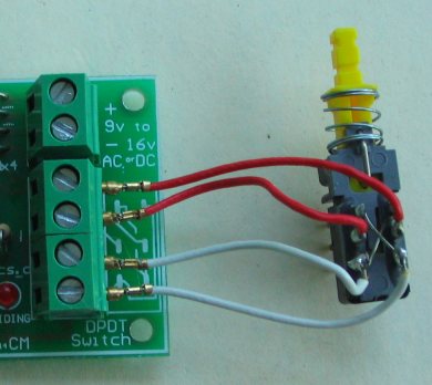
The Push Switch is provided in the
kit.
CONSTRUCTION
All the parts fit neatly on the PC board.
The transistors, diodes, electrolytics and LEDs are identified above and
the diagram shows how they are fitted to the board.
There is one unusual thing on the board. The AHEAD and SIDING LEDs are
placed in opposite directions. One LED has the cathode lead "down" and
the other has the cathode lead "up," so one LED illuminates when the
voltage is in one-direction and the other LED illuminates when the
voltage is reversed.
The screw terminals allow the board to be easily connected to your power
supply via leads into the 2-connector block. The motor connects to
another 2-screw connector while the DPDT toggle switch connects to the
4-screw block.
MODIFYING THE
SERVO
Only a motor and gearbox are
required for this project. We have used a servo because they are cheap
and compact.
Open up the servo and remove the PC board with electronics. Connect two
leads directly to the motor and re-fit the case. Check the motor on 1.5v
for activation in both directions.
Fit an arm to the output shaft and use the tiny screw provided to hold
the arm in place.
It is now ready for connecting to the track with a push-rod.
CONNECTING THE SERVO to
the TRACK
The arm of the servo produces a certain
amount of THROW.
This is the amount of lineal distance moved by each of the holes in the
arm. If you select a hole near the shaft, the "throw" will be very
small. As you select a hole further from the shaft, the "throw"
increases.
You have to match this distance with the amount of movement needed by
the moveable rails, called "blades." Once you select the required
hole, the unused part of the arm can be removed. This will allow you to
place the servo in a number of positions next to the track, so the arm
can be connected with a push-rod. This can be a small length of
spring-steel from a spring.
The servo has two mounting holes and you can make a small "L-bracket" to
fit it to the base-board. Otherwise it can be glued in pace with clear
silicon sealant. Make sure the action of the servo produces a small
amount of pressure to keep the blades against the fixed rails when it
reaches the end of travel in each direction.
|
Point Controller |
|
3 - 1k 2 - 2k2 2 - 4k7 2 - 100n monoblocks - 0.1spacing 4 - 100u 25v electrolytics 1 - BC337 1 - BC557 1 - 3mm red LEDs 2 - 3mm green LED 4 - 1N4004 diodes 1 - 7805 regulator 4 - 2-Connector terminal blocks
1 - DPDT push-switch |
5-6-2014