SIGNAL
MODULE
Page 1
Go to P2
![]()
Signals that ACTUALLY operate add a high degree of realism to any
model railway as well as being something additional for viewers to watch.
Unfortunately they are sometimes omitted due to the complexity of controlling
them realistically. This article describes a module than can be readily fitted
into an existing layout and used to control either two-aspect or three-aspect
signalling systems.
It can even provide a simple form of automatic train
control by deadening blocks to prevent trains from running into each other. On
real railways, signalling systems are varied and complex depending on who
designed them and where they are, but their primary purpose is always the same;
to stop trains colliding with each other.
On model railways their function is a
little different. Sure they can be used to stop trains colliding, but should
this unfortunate event occur, the damage will be minimal, and there will be no
loss of life.
|
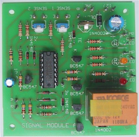
The assembled Signal Module showing the placement of the components. Notice: the pins in the PCB show where wires are connected. |
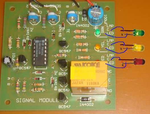
Connecting the LEDs to the Signals
Module
|
The circuit diagram of the Signal Module. The circuit consists of four major blocks: Detectors, Delay, Gating and Drivers. Each is explained in the text. |
The second difference between real
signalling systems and those on a model railway is the signal-man or lack there
of. Most model railways are operated either solo or on a one man per train
basis, leaving no-one to look after the signals. It is therefore fairly
important that the signals be able to look after themselves. As I see it, the
primary function of signals on model railways is to look the part, just like
other items of scenery.
Most modellers will not be able to
achieve an exact miniature of a real signalling system, due to the time and
effort involved. The commercial signals that are available in most model shops
are often not very accurate and being modelled after a type of signal used in
another country they are not really appropriate. Unless the individual wishes
to make his own signals, he will have to settle for something that looks
similar enough to fit the part. So with this in mind, I have developed a simple
system using modules that can be used either as stand alone units or connected
together, rather than attempting to exactly replicate a real system. They work
with single direction traffic only. Two systems would be needed if they are to
be used on a stretch of track that sees traffic in two directions. The system
for the opposite direction would have to be switched off to stop it interfering
with the one in use. My model railway has a preferred direction of travel
because of the way the points have been laid out, so I have signals facing in
only this direction.
I should point out here that for a
three aspect signalling system, at least four modules are required. For a two
aspect signalling system, three units are called for, but due to the stand
alone nature of this circuit when used as a two aspect system, it is possible
to use only one module.
The modules will drive either the bulbs
used in commercial signals or LEDs. While I'm on the subject of LEDs and
lamps, I feel it is a good idea to replace the grain of wheat lamps in the
signals with 3mm LEDs for several reasons. LEDs last a lot longer than lamps.
In fact, under normal operating conditions, a LED should never burn out. The
more common opaque LEDs give a much more even light than a lamp, and unlike
lamps, there is no coloured paint to chip off. LEDs draw about a quarter of the
current, making less demands on the power supply. LEDs are shorter than lamps,
and have a lens that looks the part. The final point of the argument is price.
Last time I saw the price of a lamp, I couldn't believe it. They were about ten
times the price of a LED!
ABOUT
THE CIRCUIT
The circuit consists of four basic parts. The first section is the train
detector or sensor, which is mounted under the track between the rails. The
second is the adjustable delay that controls the length of time the
signal remains red. The third section of the circuit is the gate array that
determines which light should be on, depending on the status of both the
current and next blocks. The final section of the circuit drives the lamps and
relay.
The first section to look at is the
delay. It is the delay that makes these signals so easy to use. My original
design used flip-flops to remember whether a train was in a block (section of
track between signals) or not. There was no way that a train could creep into a
block unless the train in front had reset it by moving into the block after it.
This was fine, except for a couple of problems. All blocks had to be manually
reset on occasion. A shadow passing over the sensor of an empty block was
enough to lock the system. It was also very difficult to deal with trains that
entered or left the main line. By replacing the flip-flop with a delay, you
achieve a very similar result without the above problems.
A train passing over a sensor will set
the signal to red, and deaden the block behind it. The delay will be long
enough for the train to reach the following block before the red period is
over. Even if the train doesn't quite get out of the block in time, and the
following train starts moving, it will not be long before the first train
reaches the next signal and deadens the block behind it, once again maintaining
a minimum distance of one block between the trains.
The only time there will be problems is
if the first train comes off the track. The delay will eventually end and allow
the following train to enter the same block, resulting in a collision if you
don't stop it manually. Unless you are a speed maniac, or just love expresses,
this should not worry you.
Each signal module has two optical
sensors, one or both of which may be used. The first sensor is placed under the
track, one locomotive length into the block (so the train doesn't stop itself!) The second may be placed further along if the block is exceptionally
long. If you have two lines coming to a junction, a sensor can be placed in
each line and the whole junction made one block, ensuring that only one train
can approach the set of points or crossing at a time. If you do not require the
second sensor, place a link on the PCB where the second sensor would normally
be connected. Failure to do this will result in the unit permanently staying
red.
The sensors use a MEL-12 Darlington
photo-transistor as the active element. Light falling on the junction of the
first transistor in the Darlington pair has the same effect as applying a
voltage to the base of the device. It turns the transistor on. The degree of
saturation, or how hard the transistor pair is turned on, depends on the
intensity of the light.
Therefore when light is falling on
SENSOR 1, it will hold the input of the Schmitt inverter IC1:F (pin 13) LOW via
R3. When a train casts a shadow over the MEL12, the transistor will not be
turned on as hard, allowing its collector to be pulled up by R1 and RV1. When
RV1 has been adjusted correctly, the voltage at this point will rise over the
input threshold on the Schmitt inverter IC1:F (about 2/3 of the voltage on
which the chip is being run, in this case 8 volts) and its output will go LOW
(to 0 volts).
I should also mention here that these
sensor circuits behave quite differently under various light conditions. They
are very sensitive under fluorescent lights, but under incandescent lamps, they
are harder to trip. If you find you have problems, you may need to change R1
and R2. Reduce them if you can't make the signals go red, or increase them if
the signals won't return to amber or green. When you are making the
adjustments, the delay can be disabled by leaving C1 off the board or shortened
by clipping a 1k resistor between the 12 volt rail and the collector of Q1.
D1, D2, R5 and IC1:B form a NAND gate.
When a shadow falls on either of the sensors, the NAND gate's output will go
HIGH (to 12 volts), switching on Q1. This will discharge C1, sending the output
of IC1:C HIGH. When the train is no longer over either of the sensors, the
output of IC1:B will go LOW again, switching off Q1. C1 will charge through RV3
and R7. When the voltage on the capacitor reaches the input threshold of IC1:C
the output will revert to being LOW.
Whenever the output of IC1:C is HIGH,
Q2 and Q3 are turned on, pulling in the relay and lighting the red LED. The
inputs of IC1:D and IC1:E are both jammed HIGH by diodes D3 and D5. This
ensures that both Q4 and Q5, and thus the amber and green LEDs, are off. The
output of IC1:C is also sent to the signal module controlling the previous
block.
If you look at the diagrams below, you will see there are several ways in which the signal
modules can be wired. Each method had advantages and disadvantages. Choice of
the most suitable depends on which advantages you prefer.

|
This diagram shows the simplest way to connect the Signal Modules together. This system is described in detail in the text. The following diagrams show more complex, but more realistic ways to wire the modules. |
We will now look at three blocks to describe how they interact. The blocks are in the order A, B, C. See the diagram marked "System A". The train has just left block B, entering block C. The signal at the start of block C has just gone red.
The train had tripped the sensor and output of the delay in block C is HIGH. It turns on the red lamp driver and the block deadening relay driver, switching off power to the track in block B, while jamming the green and amber drivers off via D3 and D5. The output of the delay is also sent to the previous signal module, in block 8.
The output of the delay in the block B module would now have gone LOW again. This enables the amber and green gating. The delay output of block C (still red) will now select the amber light at this signal by jamming the green driver off via D4. Note that even though the lamp has gone amber, a train may not proceed into block B because the block is still deadened by the relay in the block C module. However, because the module in block B is not RED, a train may move into block A.
Back at block A, it has been a long time since its delay went low, enabling the amber/green gating. As the delay output of block B is now also low, the block A signal will display green. The output of IC1:E jams the amber light off via D6. This is the natural or "rest" status for a signal module.
This is the system I prefer because of its simplicity, but some may not like the idea of a train sitting at an amber light. There are a couple of solutions. One way is to move the actual signals one block ahead, to the beginning of the section of track they control. See the diagram marked "System B". This has the disadvantage that a signal will remain green as a train passes it changing to red only when the train reaches the next signal. I would not recommend moving the sensors one block in the other direction instead of moving the signals, unless the wires to the sensors can still be kept as short as possible. Due to the sensitive nature of the delay, it is possible that electrical noise generated by the trains may cause false triggering if the sensor wires are too long.
The other solution is to put in more isolated sections of track. Instead of each block being one isolated section, it must become two, a short one (about a loco length) just before the signal and a long one which is the rest of the track between the signals. The short section of track is connected to the deadening relay, stopping any loco just before a red light. The other longer sections from all the blocks from are connected together and back to the controller. This means you have full control over the speed of the trains at any position on the loop except immediately in front of a signal that is red. See the diagram marked "System C".
In set-ups such as these, there is no individual control of the trains if you have more than one on the loop at a time, but it should stop the faster ones from catching up to the slower ones.
If you only ever run one train on your
layout at a time, or if you feel you don't require the block deadening
function, it may be ignored. The signals will still work as described above.
Use the "System F” drawing when wiring the modules.
If you wish to use the signal modules
as stand alone units, or to drive two aspect (red/green) signals, it can be
easily achieved by leaving out the wires that link the modules. Note that
leaving out this wire forces the unit to operate as two aspect. It is not
possible to run the circuit as a stand alone three aspect module. When using
the block deadening function with two aspect signals, it will be necessary to
position the signals one block ahead (System D) or to use the long/short
section method described above (System E). Otherwise, you will have trains
sitting at a signals while they are green!
|
System B overcomes the problem of trains stopping at amber lights, but leaves a green light at the beginning of the block containing the train. It is the second easiest way to wire the three aspect system. |
|
System C requires more track cutting and wiring than the previous two systems, but operates in the most realistic manner. |