|
SOLAR TRACKER-1 |
|
|
This project will improve
the output of your solar panel by about 40%. It uses a motor and
gearbox from a 3.6v power screwdriver, however a number of different
voltage motors can be used. The project has its own 6v power-supply made
from five 1.2v NiCad cells and a charging circuit using a separate 3v to 6v solar
panel to make the project self-sufficient and universal.
It has one advantage over many of the other designs. It can be connected
to an existing solar panel that is hinged or has a pivot-point so it can
move to align with the sun. You do not have to add any gear-wheel to the
panel as it can
be adapted to move the panel via a linkage. This is much easier to do
than adding gears etc.
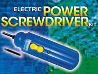
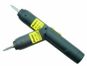
Here is just a few of the Power Screwdrivers available on the market.
Remember, you do not need an expensive unit. The cheapest will be quite
suitable, providing it is 3.6v or 4.8v or 6v.
This screwdriver is not suitable.
It runs on 2 AAA cells
and will not have the torque we need
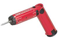
This 2.4v model costs over $100. The voltage is too low
as it will require a very high current
This 6v models costs $20.00
It comes with 4 Alkaline cells but no charger
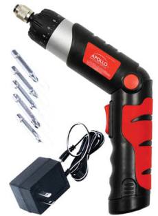
This $25.00 4.8v model comes with charger

Another $25.00 4.8v model with charger
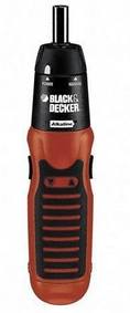
This $18.00 3.6v model does not come with a charger
The 3.6v power screwdriver is available from a number of electronics
shops, hardware suppliers and warehouses for between $10.00 and $20.00.
You do not need a charger but you will need two more NiCad cells (from an electronics store at a cost
of about $2.50 each).
Here is the cost of some of the other components: The threaded rod costs about $5.00 plus $4.00 for
wing nuts. You will need Solar Tracker-1 kit $15.00 plus some wood to
hold the motor and gearbox and about $15.00 for 6 solar cells to produce a 3v
(100mA) solar panel. Alternatively you can get a 2v solar panel and 1
NiCad cell from a Solar Garden Light for $5.00. You will need two of
these. The solar panels will need to be placed in series and connected
to the booster-circuit on the Solar Tracker-1 PC board, to produce the
voltage required to charge the NiCads.
You will need eight solar cells (100mA type) to produce a 4v solar panel or six solar cells (200mA type) to produce a 3v solar panel to maintain the charge in the NiCads
We have included a boost-converter circuit to take the voltage from a 3v
to 6v solar panel, so it will charge five NiCad cells. Normally a
6v solar panel will not do this as you need a small "headroom voltage"
to delver a current to the cells. This means you need a solar panel with
an output of at least 8v to charge the cells and this voltage is
generally only available when the panel is receiving very bright
sunlight. Our design will allow a panel with an an output as low as 3v
to charge the 6v set of NiCad cells. We need a charging current of only
about 30mA to replace the energy taken from the cells during normal
operation so almost any small solar panel can be used. But if you are
using a 6v motor, the requirements will increase to abut 100mA
We have suggested using NiCad cells because they are cheap and you
will possibly have some lying around your workshop. We do not
need high-capacity cells as they are constantly being charged and we only
need them to convert a low-current device (the solar panel) into a
high-current supply.
The motor from a 3.6v electric screwdriver is ideal, as it is cheap, comes
with an inline planetary gearbox and 3 NiCad cells. You only
have to find two more cells and this part of the project is ready.
If you want to use a 6v (or higher) motor, a few components will need to be changed.
The supply will need to be 8v (or higher) and a 78L05 voltage regulator will be
needed to supply 5v for the micro. The two LEDs will need to be replaced
with 4 LEDs (or more) as shown in the modified circuit. The LEDs operate
as a zener diode when the supply voltage is higher than 5v as the output
of the chip is clamped at 5v via the components in the chip and the
voltage on the base of the BC557 must not be lower than 0.6v (with
reference to the supply rail), otherwise the transistor will not turn
off. The LED also shows when one of the arms of the H-bridge is
operating and this arm will also turn on the diagonally opposite arm.
THE
PLANETARY DRIVE
The output from the planetary drive is approx 100 to 200RPM and although
it has considerable torque, it cannot be used to directly control a
solar panel. The RPM is too high and if connected to the panel, the
panel can easily turn the motor "in reverse" if there is a wind. This
may not be a problem, but it doesn't provide an ideal set-up.
Further reduction is required. The best idea is to fit a threaded rod to
the hex output of the power-screwdriver and place two nuts on the rod at
a short distance apart so the rotary motion can be turned into linear
travel. This travel can turn the solar panel 90 degrees or more to pick
up the peak output of the sun, via an arm called a linkage or by a pin
or finger on the actuator.
These two nuts will run up and down the rod when the rod is turned and
they are held in place so the linear motion provides movement without
jamming - if you use a single nut, it will try to bend-over on the rod
when a load is applied - and this will stop the motor.
A simple bearing will hold the end of the threaded rod and the slide
containing the nuts will provide "purchase" to prevent the rod bending
and transfer the linear motion to an arm or bracket to move the solar
panel.
This arrangement will prevent any wind pressure from the panel causing
the motor to drive in reverse via the gearbox.
Alternatively you can use a Meccano worm drive but you will have to
mount the worm and gear wheel using shafts and these components will
cost more than $20.00 from a supplier. They are also much weaker than
our suggestion.
LIMIT SWITCHES
"Limit of travel" must be
detected at each end to prevent the "linear actuator" reaching the end
and damaging the project.
The motor, gearbox and nut arrangement has so much torque that it will
tear the assembly apart if allowed to travel too far at either end.
A simple method is to place a limit switch at each end to detect this
travel but a switch is very unreliable when exposed to outside weather.
We have designed a very clever method to detect the end of travel. It
consists of a metal object (such as a nut) attached to the shaft so that its
rotation can be detected by an
inductor that is oscillating at a fairly high frequency. The inductor is part
of an oscillator in which the frequency is known by the micro. When a
metal object comes close to the inductor, the frequency is lowered and
this
is detected by the program.
This arrangement has no moving parts and is very reliable.
But we need to detect two things. The limit of travel in two directions.
You can place an inductor at both ends of the travel but we have
improved on this by using just a single inductor and counting the number
of turns of the threaded rod.
To make sure we detect the nut correctly, we stop the motor just after a
detection. This means the nut will never stop in front of the inductor
and create a false reading.
TRAVEL DISTANCE
The TRAVEL DISTANCE is the
distance the set of two nuts is allowed to travel via the program in the
microcontroller.
We have set this at 250 revolutions. This will produce travel of about
35cm and depending on where the output of the actuator is connected to
the solar panel, it will provide rotation of 90 degrees or more.
THE H-BRIDGE
The output of the circuit drives the motor via an H-Bridge.
It is called an H-Bridge because it looks like the letter "H."
We have designed a very unusual arrangement of NPN Darlington
transistors and it is very successful. The current consumption of the
bridge when not driving the motor is ZERO and the voltage-drop across
the bridge is acceptable, for the current it it delivering.
We have used Darlington transistors as we need a very high current to
start the motor (called the stalled current or starting current) and since we have a
maximum of 20mA from the chip, we need a very high gain to get 4 amps
through the bridge for the starting-current.
At 4 amps, the collector-emitter voltage-drop for a BD679 is 1.1v but if
4 amps is divided between two transistors, the voltage-drop is 0.9v. We
need as much voltage as possible to provide the motor with starting and
running torque and that's why we have used the output transistors in
pairs.
Each pair of transistors will need heatsinking and the 4 heat
sinks must not touch each other as the collectors are all AT DIFFERENT
POTENTIALS at different times.
The running current is about 2.5amp for the motor we have used but this
will depend on the motor you use.
The circuit will allow currents of 4-6amp for short periods and this
will depend on the size of the heatsinks (as the limiting factor) as the
transistors will get very hot with small heatsinks.
Only 1 drive line is needed for forward and 1 for reverse. The lower
transistor is turned on via the chip and the diagonally-opposite upper
transistor(s) is tuned on via a resistor and LED to provide a path for
the forward or reverse direction.
USING A 6v MOTOR
A 6v motor can be used but the supply will have to be increased to
8v (6 NiCad cells = 7.2v 7 NiCad cells = 8.4v) and you will
need to add the 78L05 voltage regulator to deliver 5v to the
microcontroller.
A 78L05 consumes 6mA and the micro takes less than 1mA when "sitting
around" doing nothing, and this current must be taken into account when
charging the NiCad cells. If the sun shines 6 hours per day, this
equates to 24mA + 4mA during charging-time, just to maintain the charge in the cells
for this requirement.
You will need eight solar cells (100mA type) to produce a 4v solar panel
or six solar cells (200mA
type) to produce a 3v solar panel to maintain
the charge in the NiCads, taking all the variables into account and the
energy required by the motor. The solar panel will then connect to the
"booster circuit" to produce the voltage required to charge the NiCads.
THE CIRCUIT
Most of the operation of the circuit has already been covered. The only
thing that cannot be described is the actual voltage drop across the
output transistors due to the type of motor you will be using.
BD679 transistors have a collector current of 4 amp and are very low
cost. That is why we have used them.
To fully saturate the BD679, we need to deliver the full capability of
the micro (20mA) to the base. This will turn it on fully and reduce the
collector-emitter voltage to the lowest possible. Remember, the 20mA
from the micro is being divided between two transistors, so that each is
getting only 10mA to turn it on.
Theoretically the transistor should saturate with a base current of only
1mA, but even at 5mA, the transistor is not turned on fully and will
heat-up due to the higher collector-emitter voltage.
The output pulses to the motor are not PWM (Pulse Width Modulation) but
consist of a short pulse that is long enough to start the motor turning
and produce three revolutions of the output-shaft.
During this time the signal from the LEDs detecting the sun's brightness
are monitored to see if they both produce an equal output. When this
occurs, the signal from the rotating nut on the rod is detected and the
motor is stopped immediately - if not, the motor is turned for
three more revolutions. A time-delay of 5 minutes is then executed and
the process is repeated.
Stopping the nut (the shaft) in a known angular position prevents false
detection of the rotation of the threaded rod. This is to keep track of
the position of the actuator.
The actual position of the actuator is not known.
It is assumed to be in a particular position due to the setting-up
procedure. When the chip is programmed, a starting value of 50 is placed
in EEPROM. This represents 50 turns of the threaded rod - away
from the motor. You must now add another 20 turns so the actuator
will never come closer than 20 turns to the motor.
This gives you a margin of clearance.
The program will take the actuator another 200 turns (threads) away from
the motor-end and obviously the second nut on the actuator will be a
further
70 threads away.
This will use almost all the 600mm threaded rod and leave a safety
margin at each end.
THE POWER SUPPLY
To keep the "line losses" as low as possible, the NiCad cells must be
close to the motor and the wiring must be thick hook-up wire (flex). The
solar panel can be remote because the current is only very small and the
length of the wiring is not important.
TESTING
We are dealing with a NiCad power supply that can deliver a high current
and the transistors will "go up in smoke" if a short-circuit is present.
To avoid this when setting up and testing the project for the first time, use ordinary carbon-zinc cells.
Solder the components on the PC board for the sections you will be
using but do not fit the chip.
Connect the power supply and the motor and get a jumper lead. Connect
the jumper lead to the positive rail and very briefly touch the other
end on one of the 220R resistors that connect to pin 6 or 7 of the chip.
One of the LEDs will illuminate and the motor will turn in the clockwise
direction. The other resistor will make the motor turn in an
anti-clockwise direction.
Make sure your supply will actually turn the motor by connecting the
motor to the battery.
If the bridge does not drive the motor, either one of the opposite-pair
of transistors is faulty or both have a fault.
If the LED illuminates, the lower transistor is turning on and the fault
will be in the upper Darlington transistor or the PNP driver.
Keep the jumper connected and use another jumper to connect the positive
rail to the base of the upper Darlington transistor. This will bring it
up to the positive rail as it is an emitter-follower. If this does not
work, you know where to look.
You have now tested
all the components in the forward drive section of the H-bridge. The
other legs are the same. When it works, you can use the NiCad cells.
Use a jumper to test the motor for
10 seconds by connecting it to one of the 220R resistors. The heatsinks should not get very hot.
THE "BOOST" CIRCUIT
The "Boost Circuit" is actually a fly-back arrangement using an inductor
to produce a high voltage. It produces spikes as high as 30v (no load)
but these are reduce to the battery voltage and are absorbed by the
NiCads as energy and get charged.
This circuit will produce a charging current on a cloudy day and as the
sun increases in brightness, the current will increase.
You will need eight solar cells (100mA type) or six solar cells (200mA
type).
You can change the wording and add more features. To do this you need a
programmer and software. For details on this, see
Pick A
PIC Project.
PROGRAMMING A PIC
CHIP
This project is also designed to show
how to program a very small 8 pin PIC chip.
It is part of a course on "PROGRAMMING PIC CHIPS."
Each project adds another area to the "design library" and this project
shows how to interface three more devices. These are:
1. Input sensors,
2. Driving an oscillator and detecting its change in frequency, and
3. Driving an output.
The chip used for this project is an 8-pin PIC12F629. Two
lines are used for the motor, two for detecting the sun and one for the
position of the actuator, via an oscillator feeding an inductor.
If you want to change or improve the program, use our technique of
copy-and-paste where you change only a few instructions at a time.
This project offers areas for experimentation. It shows how
interface external devices to a microcontroller
THE PROGRAM
Each l
To change any of the content of the program you will need a
programmer and the software that drives the programmer as well as an
assembler (MPASM) .
All these things are covered in an article:
Pick A
PIC Project.
CONSTRUCTION
A full kit of components for Solar Tracker-1 is available from
Talking Electronics. It contains
a
pre-programmed chip and the parts shown in the parts list.
Some of the parts will not be needed for the 6v version but we have
included everything so you can create any version of the project.
Before starting assembly, you need to work out which parts of the
circuit you will be using and which links to add to by-pass the circuit
that is not required.
GOING FURTHER
Ho
This project is just one idea for a range of cards that are "different from the
rest." The card market is enormous and when you realise most cards
are poorly designed, you have a goldmine of potential.
Other ideas are a combination-lock game, a counter, a ladder
game, and similar things that would make buying a card a
rewarding decision.
Cards are just one area. The market is enormous and include toys and
gimmicks combined with sweets.
The PIC micro gets an idea "off the ground" and you can get your ideas into
production very easily.
It's the starting point you have always wanted.
PARTS
LIST |
|
5 - 82R or 100R
surface-mount resistors 1 - 47k surface-mount resistor "103" 5 - 3mm or 5mm red or white LEDs 1 - 8 pin IC socket 1 - pre-programmed PIC12F629 IC "SKY" 1 - 30cm thick tinned copper wire 1 - 40cm 0.2mm enamelled wire 1 - weight for inertia switch 3 - button cells from 12v lighter battery 1 - 1m very fine solder 1 - Solar Tracker-1 PCB |
Here are the files:
SkyWriter.asm
SkyWriter.hex
;Sky12F629.asm ;Sky writer with 5 LEDs for PIC12F629 13-5-2010 list ;oscillator calibration org 3ffh movwf OSCCAL end |
10/7/2010