|
SQUARE
WAVE |
A handy piece of test equipment for many applications
Kits are available from Talking Electronics
|
A square-wave oscillator |
|
The Square Wave Oscillator |
|
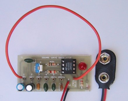
The Square Wave Oscillator circuit |
This project is a piece of test equipment. It's a square wave oscillator with 6
selectable frequencies from 1Hz to 100kHz, incrementing in decade values.
It's most useful application is as a Signal Injector for radios and TV's. A
square wave is the most suitable for testing the IF (Intermediate Frequency)
strip as the signal will pass through the IF transformers without any
attenuation, no matter what the tuned frequency of the circuit.
Normally only a sine wave of the correct frequency will get through but a
square wave can be considered to be a composition of all of the multiples of a
sine wave and no matter what the frequency of the tuned circuit, it will be
processed.
This project can also be used to test digital circuits by providing a clock
pulse, using one of the 6 frequencies to determine if a circuit can be
"clocked."
It can also check audio amplifiers for gain and distortion, (providing the
correct attenuation is provided on the output of this project).
In fact it's an invaluable piece of servicing equipment and I have used a
similar device for testing the IF strip of TV's on the odd occasion when a
fault developed, and it located the trouble very quickly.
The 6 frequencies are selected with a jumper lead and increment in decade
values as is standard with test equipment. If you want the frequency to be
variable, you can use a pot between pins 6 and 7 of the 555, instead of the capacitors, but keep in mind that you
cannot get the same range by using a single pot - that's why we have used capacitors.
CONSTRUCTION
All the parts fit on a small PC board and the overlay shows exactly where
everything goes.
Fit the IC socket first and note the position of pin 1 as the chip has to be
fitted correctly if you don’t want it to be damaged.
Make a short wander lead with hook-up wire and tin the end so that it fits into
the hollow pins. Put the lead into the 1Hz position and connect the battery. You
will see the LED flash on and off to prove the circuit is working.
Change the lead to one of the higher frequencies and inject the signal into the
IF strip of a radio. Start at the volume control end and work your way to the
antenna. As you move through the strip, the signal strength will increase and
you should compensate for this by adding resistors and capacitors on the output
to reduce the signal. You can also check any of our FM transmitters by picking
up the tone on any radio tuned into the transmission.
In a future article we will describe how to use this project to test different
types of equipment.
|
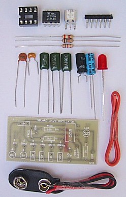
The Square Wave Oscillator kit |
|
PARTS LIST |
| 1 - 1k 1 - 3k9 1 - 10k 1 - 68k 1 - 100k mini trip pot 1 - 100p ceramic 1 - 1n greencap 2 - 10n greencaps 1 - 100n greencap 1 - 1u 16v electrolytic 1 - 10u electrolytic 1 - 5mm red LED 1 - 555 timer 1 - 8 pin IC socket 6 - hollow pins 1 - 10cm hook-up wire 1 - 9v battery snap 1 - Square Wave Oscillator PC Board |
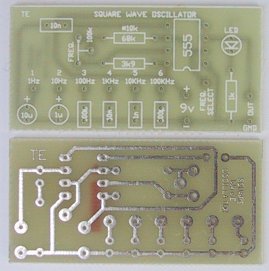
| The Square Wave Oscillator PC board |
![]()