|
STRESS METER |
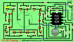
This project uses the "18 LED Display-1"
Order kit
P2
![]()
|
|
STRESS METER CIRCUIT
(Stress Meter circuit
is the same as 18 LED Display
circuit)
(The LED numbers follow the LEDs on the PC board)
I visited a games shop recently and saw a
simple game called "STRESS METER". It consisted of 16 LEDs in a circle
with two touch pads. By placing your fingers on the touch pads, the
circuit started and ran the LEDs in a "chaser" pattern around the display,
with a beep each time a LED was illuminated.
The circuit gradually slowed down to a random LED and the display showed
"how stressed you were."
"What a wonderful idea for the 18 LED Display-1" I thought.
And here it is.
The program for this game is complete and ready to run, but it can be improved and more
features can be added. This is the purpose of this article. After you
see how the sub-routines are put together, you are invited to add more
ideas of your own.
When the project is turned on, the piezo beeps every few seconds with a
"beep-beep" to let you know the game is switched on.
By putting your fingers on the touch pads, the LEDs illuminate in a
circle. Each time a LED is illuminated, the piezo produces a beep.
The pattern gradually slows down to a final LED.
The piezo emits a "Rising Sound" and the game starts again.
Obviously the circuit has nothing to do with your stress level. It is
purely a random number generator.
All the sub-routines have already been presented in
other projects so it's just a matter of combining them to produce the
game.
WHERE DO YOU
START?
Whenever you have a task in front of you, where do you start?
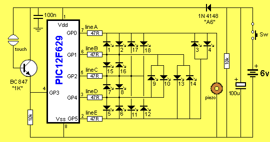
In this case it is "accessing the LEDs."
Each LED has a defined set of outputs that must be HIGH and LOW, with
all other lines "input" (so they do not upset the brightness of the LED
being driven).
The circuit diagram shows how each LED is accessed.
You can make a test-device by connecting two cells together and placing
a 220 ohm resistor on the positive lead. By probing each pair of outputs on the chip
(with the chip removed from the socket) you will see the corresponding LED
illuminate.
This data is then placed in a sub-routine and represents the first
sub-routine of your program.
The next sub-routine to add is a delay.
You can then create a Main routine that accesses each LED and
illuminates it for a short period of time.
Each sub-routine is added to the program in alphabetical order so it can
be found quickly when the program is very large.
Del_1 is a "do-nothing" routine called a "Nested Delay." Two or more
files are required to produce a delay.
The maximum value a file can hold is FF. This is a hex value equivalent
to 255. If you create a loop and decrement the file to zero, the maximum
"delay-time" you will create is very short as each instruction takes
only 1 micro-second. Each loop will take 3 - 5 microseconds, so the
total time will be less than 1 millisecond.
If we place another loop around this, we create an inner loop and an
outer loop.
The micro executes the inner loop and then one loop of the outer loop.
The result is 255 loops of 1 millisecond. This produces a total of about
0.25 seconds. If we pre-load a file with a value, we can adjust the time
for the delay. If the files are not pre-loaded, the delay uses the
unknown value in the file. If a file has been decremented to zero, (as
with the inner loop) it will contain 00 and will immediately be
decremented (or rolled over) to FF. That's why it will produce 255
decrements.
In the following delay, file B has been pre-loaded with 20h:
| Del_1 DelX |
movlw movwf decfsz goto decfsz goto retlw |
20h fileB fileA,1 DelX fileB,1 DelX 00 |
The next sub-routine is Beep. This produces the
effect of the click of a Wheel Of Fortune," as it rotates. All sounds
are actually a square wave. When the HIGH time is equal to the LOW time,
the square wave is called a "regular" square wave. The high time can be
longer or shorter than the low time but this changes the sound a very
small amount, when we are talking about a "tone" (a constant frequency).
To produce a tone (a beep) we need three files.
1. HIGH time
2. LOW time
3. Duration of the tone.
The HIGH time file can be the same as the LOW time file, but each file
must be loaded with a value before each part of the cycle as it comes
out of the loop with "00."
The following sub-routine is used to produce the Beep:
|
Beep Beep1 Beep2 Beep3 |
movlw tris movlw movwf bsf movlw movwf nop decfsz goto bcf movlw movwf nop decfsz goto decfsz goto retlw |
b'11111110' 05h 020h beeplength GPIO,0 80h beephigh beephigh,1 Beep2 GPIO,0 80h beeplow beeplow,1 Beep3 beeplength,1 Beep1 00 |
;make GPO output ;Piezo HIGH ;Piezo LOW |
The next sub-routine to add to
the program is:
RISING SOUND
This indicates the end of the game.
This program is more-complex than "Beep."
To produce a sound from a speaker or piezo diaphragm, the output from the micro is made
HIGH then LOW, at a regular interval. To increase the pitch of the note,
the interval of time between the HIGH and LOW is decreased. This can be
done by decrementing a file. The tone will then increase to a very high
note. The program can detect when the file is zero to end the
sound.
In the Rising Sound sub-routine, we load a file called "temp" and them
immediately load the value it contains into another file called
soundhigh for
decrementing. "soundhigh" is then decremented to zero to produce the HIGH portion
of the waveform. "temp" is then loaded into "soundlow" and decremented
to produce the LOW portion of the waveform. This keeps "temp"
available to be decremented once
after each cycle, to produce the gradual rise in tone.
| sound sound1 sound2 sound3 |
movlw tris movlw movwf bsf movf movwf nop nop nop nop nop decfsz goto bcf movf movwf nop nop nop nop nop decfsz goto decfsz goto retlw |
b'11111110' 05h 0F0h temp GPIO,0 temp,0 soundhigh soundhigh,1 sound2 GPIO,0 temp,0 soundlow soundlow,1 sound3 temp,1 sound1 00 |
;make GPO output ;Piezo HIGH ;Piezo LOW |
The next sub-routine is:
THE RANDOM NUMBER GENERATOR
One of the most difficult sub-routines to create is the random
number generator. This is because a computer is very precise in its
execution of instructions and it cannot produce a list of random
numbers.
You may have seen a random number generator program using the timer file
(TMR0). This will produce a single random number, but we need a sequence
of random numbers. It is very difficult to get a stream of random
numbers.
The only solution is to produce a random number table and access it
"half-way down" by using a starting value derived from the timer
register.
The pointer for the table is incremented on each pass of the program and
when it reaches the end of the table, it starts at the top. In this way,
even the first number is unknown and the pattern will never be
remembered by anyone playing the game.
THE
TOUCH PAD
The Touch Pad is two tinned pads on the PC board. When you touch them
with a finger, the resistance of your finger is reduced by a factor of
about 100 - 400 by the gain of the emitter-follower transistor and this
puts a HIGH on the input pin of the chip. The input impedance of the chip is fairly high (about 50k)
but when you add a pull-down resistor (to prevent stray signals being
detected by the chip), the impedance decreases. The
answer is to add the emitter-follower transistor.
THE
PROGRAM
The full program is shown on
P2 of this article.
The file you will burn into a PIC12F629 chip is: .hex
The PIC12F629 chip in the kit comes with pre-programmed "Stress."
It can be re-programmed up to 1,000 times but the best thing to do is
purchase another chip and use it to burn your own programs.
THINGS YOU CANNOT DO
The LEDs in this project are
connected to the outputs of the micro in a very special way to provide unique
access that cannot be applied to other types of devices.
You cannot connect other devices to the chip in the same way as we have
connected the LEDs due to the special characteristic of a LED.
A LED will not turn on if the applied voltage is below its
characteristic turn-on voltage.
If a LED is replaced with a piezo, for example, the voltage across the
piezo will be approx 5v, and this voltage will also appear across two or
three of the other LEDs in the display and they will also be activated
and produce a very small illumination.
That's why the piezo has to be connected between one of the outputs and the 0v
rail.
ASSEMBLY
Constructing the STRESS METER
project and testing the circuit is covered in the "18 LED Display-1
project." The only two components you need to separately identify
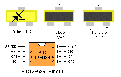
are the transistor and diode. They both look the same. The diode is
marked "A6" and the transistor is "1K."
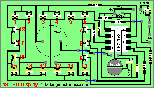
All parts mount on the top-side of the
board.
The 7 blue lines are jumpers made from enameled wire.
Parts identification
GOING FURTHER
This project offers a wide possibility for changes, improvements and
additions.
You can add a different "click" sound to indicate the wheel
advancing or another tune when the
wheel stops. You can also add an "attract mode" at the beginning of the
program, when the game is waiting to be played.
When you are adding anything to the program, only add a very small
modification and test it.
If the addition does not work, try it as a completely separate
sub-routine by starting a new project and testing it by itself.
This especially applies to sub-routines such as sounds, as they can be
tested separately.
You can also start a completely different project using the layout of
the LEDs and
piezo.
To do this, we have started to help you. If you touch the touch pads
before turning the circuit ON, the program will go to a "NEW" section
and repeat the "Rising Sound" tune. This lets you know you have reached
the "NEW" section.
In place of "NEW" you can add your own routines. You can also use any of
the sub-routines from the STRESS METER game or adapt any of the sub-routines
from our
Library:
A-E
E-P
P-Z .
WRITING YOUR OWN PROGRAM
The program for "Stress" has been written in a very simple "linear" way
that uses a lot of repeated instructions. This has been done to help beginners
understand how to create sub-routines.
Many programs are written by very clever programmers and they try to show their
skills to newcomers. The result is a failure. Things must be explained in a very
simple way so that they can "latch-on" to the concepts.
That's why this project is ideal. It starts at the beginning.
You can produce a result on the display with as little as 10 instructions.
The PC board contains a touch switch, piezo and a number of LEDS.
Although the LEDs are not accessed in the normal way, you can use the sub-routines to
access each LED (about 4 instructions) and write your own program to do
something simple - like flash a LED or produce a tone.
It doesn't matter where you start or how simple the program, the important part
is to START.
You can use the chip that comes with the kit or buy another one and keep the
original as a back-up.
Start with something simple - turn on a LED.
Then turn on another LED.
Then flash a LED
Then alternately turn on two LEDs.
Then produce a beep.
Then produce a beep-beep-beep.
Then produce a beep - beep while alternately flashing two LEDs.
This is the only way to build up your skills.
After all, this is the way the author created the Stress program.
The only way to create anything complex is to add a small bit at a time. This
allows you to fault-find a mistake or carry out corrections or modifications,
with the least amount of frustration.
If you create a lot of code at the one time and the program does not work, it is very difficult
to fault-find the mistake.
You can use some of the "de-bugging" programs and "single-step" features
provided by Microchip, but these will take you a long time to use.
They are very interesting to use as they show the content of each file before
and after each instruction.
They will also show you how each instruction works and what result it produces.
This is especially important with logic instructions (AND, XOR etc) and the
setting or clearing of the bits in the STATUS file (such as Carry, Digit Carry
or Zero).
But the fastest way to progress with a program is to use the sub-routines we
have provided in our Library of Routines - "Copy
and Paste."
The chip is like an empty exercise book.
You can write almost anything you want.
It's now up to you,
| |
|
15-1-2006