TIC TAC TOE
Page 2
CONSTRUCTION
All the parts for Tic Tac Toe can be purchased in a kit as shown in the photo
below. The only components requiring careful identification are the
LEDs. The diagram below shows how they are fitted to the board. The player LED
is red and the computer is green. Push all the LEDs until they touch the board and
make sure they are upright. Solder the leads very quickly to prevent damage to
the light-emitting crystals inside the body of the LED.
The 100n across the chip (to prevent spikes getting into the chip) has been
mounted on the underside of the board. This component is a surface-mount
capacitor (commonly called a "chip" capacitor) and will need a little care
when soldering - mainly to prevent losing it on the floor!
All the other components are easy to fit and the transistors should be pushed
up until they are slightly less than 1/4" (3mm) from the board. The
switch mounts on its side and don't forget the IC socket. We are one of the
first suppliers to include an IC socket in all kits.
The tactile switches can only be fitted with the leads on the side. They can
be fitted around either way as they are effectively double-contact devices.
When all the components are soldered to the board, the battery box fits on the
underside with a small piece of double-sided tape. Fit the chip and switch the
project on. The chip is pre-programmed and the ATTRACT MODE will appear on the
display.
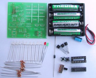
Tic Tac Toe components
Identifying and connecting a 3-leaded LED
Fitting the LEDs
Fitting the 100n and jumpers:
The 100n capacitor is a surface-mount type. It is soldered under the PC board
as shown in the diagram below.
Two jumpers are needed. They are different to a normal through-hole jumper.
There are surface-mount jumpers. Use the fine tinned copper included in the
kit to solder as shown in the diagram below:
Fitting the 100n and two jumpers
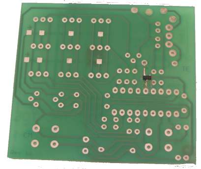
A diode has been placed on the underside of
the board
to drop the 6v to 5.4v as some PIC chip "freeze-up"
when the voltage is above 5.5v!!!
The operation of the program can best be seen from the following FLOW CHART:
The micro is constantly scanning the display and when Move or
Play is
pressed, it goes through a number of sub-routines
that fixes the player piece on the board (changes the cursor into a red piece)
and then places a computer piece (green) on the board. DISPLAY BRIGHTNESS
These operations are carried out so quickly that any interruption in the
scanning of the display is not noticed.
The program appears to have "intelligence" and when you are creating routines
such as these, the results are very rewarding. They seem to
provide an intelligent feedback that sometimes arrests your attention.
The brightness of the display is determined by four things.
1. The brightness (quality) of the LED
2. The current capability of the drive-line of the chip.
3. The scanning frequency (duty cycle)
4. The resistance of the current-limiting resistor.
The current capability of each drive-line is approx 25mA and since the
duty-cycle for each LED is 33%, the average current for a LED is a maximum of 8mA. We have
already explained one of the unusual characteristics of a
LED.
If it is driven by a high current for a short period of time, the brightness
is better than a lower, constant current.
In our case, peaks of 25mA, for a 33% duty cycle, produce a very bright output from the LEDs and
the drive-current needed to be reduced. This was done by increasing the
current-limiting resistors to 330R.
It is important that the current limiting resistors are placed on each of the
drive-lines instead of the sinking line, as the sinking transistor will be
carrying a varying current, depending on how many elements are illuminated
during each part of the scanning cycle.
With a varying current, any dropper resistor in the transistor-line will drop a different
voltage and this will produce a varying brightness.
MODIFYING TIC TAC TOE PROGRAM
The Tic Tac Toe program shows how to set up the chip to turn off
the comparators and activate the internal oscillator.
We have also provided a complete "
Library of Routines"
that can be used for this chip and
"Copy and Paste" instructions in Word format.
These two "aids to programming" are in our subscription section. An
enormous amount of time has gone into preparing the Library of Routines
and it is part of the PIC Programming Course.
You will also learn a lot by reading through the programs we have written for
the other projects on the website.
When writing your own program, start with a very simple routine. Use our
StartUp instructions (see P3 - Tic Tac Toe Program - the first set of
instructions in the program) and modify them to suit your own requirements.
FAULT-FINDING
Debugging (fault-finding) a program is one of the most difficult things to do.
It's very difficult to know if the fault is located in the section you are
working on, or somewhere else in the program.
There are a number of fault-finding programs such as single steppers, but
these don't take into account the effects of an input and you have to fiddle
around with the settings to jump over delay routines etc. I tried them all
they were very slow to implement and really didn't find the fault.
The answer is to insert a test routine (or a number of test routines) into the
program that produces an output on a LED to let you know how far the micro has
progressed through the program. If each test routine produces a different
result (number of flashes etc) you will be able to work out exactly what is
happening.
The following 3 routines were used in the development of the Tic Tac Toe
program. The first Test routine flashes the player LED 3 times. The
second routine flashes the computer LED 3 times and the third Test
routine flashes both LEDs 3 times.
|
THE DISPLAY
The 3x3 display offers a wonderful starting point for programming.
If you have ever wanted to produce "running letter displays" or "animated
screens," this is the place to start. The display on this project is as small
as you can get but it provides the understanding on how to produce a program.
It's amazing how many effects you can put on a simple 3x3 display and
the method of producing an animation is completely different to
what you may have thought.
The best method is to consider the display as very
similar to a TV screen.
The LEDs are activated via a scan routine called a RASTER.
For a TV, the raster is the white screen produced by the scanning dot and when
this dot is modulated, a picture is produced.
In our case, the top row of six LEDs are turned on for a short period of time
and then the middle row, and finally the bottom row. This is repeated very
quickly in a loop program.
Approximately 250 loops are executed in 1/4 second and this allows 4 updates
to be displayed per second.
This is exactly like the 24 updates per second for a TV.
The RASTER ROUTINE does not illuminate the display. It is a program
that loads data from a table and put the data on to the display. It takes a byte of
information from a table to illuminate any or all the LEDs on a row. The following diagram shows the 6
bits that turn on the LEDs. Only bits 0, 1, 2,
3, 4, 5 are used.
When the sinking transistor is turned ON, the LEDs
are illuminated.
The arrangement of the lines, with Bit0 on the right, makes it easy to work out the table values for all
the combinations. There are 64 different possibilities for each row. The table
below shows the combinations:
Once the values are known for each combination, it is just a matter of placing
them in a table.
Any animation consists of "frames." The following 4-frame animation creates a "spinning
rod:"

To produce each frame, 3 bytes are needed. The values for the 4 frames are:
19h
19h
19h ---
16h 19h 25h --- 15h 2Ah
15h --- 25h 19h 16h
When the data for the 4 frames is placed in a Table and the RASTER sub-routine is activated, the display will produce:
![]()
The Raster sub-routine is shown below. The reason why a Raster routine is
the best approach is simple. It gives you full control over the display with a
group of 3 bytes. The alternative approach is to access each LED individually.
Rows can be accessed easily by adding the value for each LED and outputting to
port B (port 6). But if you want to access 3 LEDs in a column, they cannot be
turned on at the same time as the current taken will be more than the maximum of 25mA drive-current for a line.
THE RASTER ROUTINE
With our method of driving the 18 LEDs of the display, it is not possible to
individually access say the top left red LED and the bottom right green LED.
In other words it is not possible to "dump" a value and turn them on. If you
do this, you will find all the left-hand red LEDs in the column will turn ON
and all the right-hand green LEDs will turn ON.
But if you put this requirement into the Raster routine, the display will
produce the required illumination and we have achieved the effect.
Once you understand the reason for scanning the display and how it operates, you are on your way to designing some impressive animations.
There are hundreds of effects that can be generated on the 3x3 display,
including flashing, changing colour and all types of movement. The "attract
mode" of the TIC TAC TOE project shows a number of these effects.
The Raster routine can be used as a completely separate routine to produce all
types of effects on the display. All you need is the Raster
sub-routine, a Table and a Delay sub-routine. These are shown
below.
We will now explain in full detail, how the Raster routine works.
The Raster routine is very similar to the "white screen" of a TV.
It does not put any "pictures" on the display. It only turns on each row for a
short period of time and loops for 0Eh loops. Each loop consists of turning on
the top row, middle row and bottom row. This must be done very quickly so that
the whole "screen" appears to be illuminated. After 0E loops, the program is
ready to pick another set of three values from the Table.
The Table
provides the values that put the picture on the display. During each loop, the
table-pointer is incremented (lines
16
and 23).
At the end of the loop, the table pointer must be decremented three times to
get is back to the beginning of the three bytes (lines
30
and 31).
During this operation the micro is executing the "inner loop" of the program
(lines 5
to 33)
and is showing a "cell" or "frame" on the display.
So that the "cell" is visible for about 250mS, a very short Delay routine
(approx 1mS) must be
included to so that a total of about 250,000 instructions are executed. The
delay routines include instructions to look at the buttons to see if they
have been pressed. This is the best place to put these instructions as the
delay routine is constantly being executed and a fast button-press will not be
missed.
After 0Eh loops of the program are executed, the micro goes to the outer loop
to pick up the next 3 Table-values. It increments the table-pointer 3 times,
resets the loop-counter and displays the second frame.
The program checks for the end of the table. By providing three
RETLW 0FFh in the table, we
make sure the program picks up one of the end-of-table indicators, just in
case the table does not contain sets-of-three bytes.
Now, let's look at some of the bits of the program.
To detect the end-of-table, we Exclusive-OR the value 0FFh from the
table with the same value (0FFh) that has been placed in the instruction.
This value is called a literal or number and is the "L" part of the
instruction XORLW. We have chosen 0FFh as it will never be used as a table
value.
The instruction,
XORLW 0FFh places the result in W and each bit from the table is compared with
the same bit in the value 0FFh. Since all the bits in the literal are "1," the
result will be "1" when one (and only one) of the bits is "1."
In our case, the result for each operation will be "0" as both bits are "1."
The final result will be 0000 0000.
The next instruction BTFSC 03,2 tests the zero flag. Since the
answer is zero, the zero flag will "pop up! In other words it will be
SET.
The next instruction, BTFSC 03,2 looks at the zero flag. If
the zero flag is clear, the micro will skip the next instruction and carry out
the instruction that follows.
To revise: If the table value is the same as the literal, the zero flag will
be SET.
The program appears to be very long but
is really a group of instructions, repeated 3 times.
It can be modified to include a delay value for each "frame." This
will allow fast and slow motion to be included.
|
SEND US YOUR PROGRAM
Send us the program you have created for your effect(s) on the 3x3
display and we will put it on
this page, along with an animation.
Here are some sample animations:


You can design another game for the 3x3 matrix such as a REACTION
TIMER. The PC board and micro is like a blank book. You can write any program for the
microcontroller and produce any type of game that uses the 9 LEDs and two
push buttons. There are almost no restrictions. You can completely re-write
the Tic Tac Toe program using a single algorithm in which the micro
"learns" the rules of the game. This generally requires a lot of non-volatile
memory to store the results of each game. The 16F628 has 128 bytes of
non-volatile memory and 224 files for use as a "scratch-pad" - the data
in the 224 files will be lost when the power is removed.
GOING FURTHER
The 3x3 display can be increased to 4x4 5x5 or 6x6 using the PIC16F628. A larger
display will require additional chips and increases the complexity and cost of
the circuit enormously.
Our design is the first multi-coloured display to be presented, so none of the
larger projects on the internet, can be used.
Almost all the effects for a large display, can be done on the 3x3
and if the demand is sufficient, a 5x5 (or greater) will be produced.
![]()