|
Tunnel Stretcher |
15-10-2006
Do you find your tunnels a bit short? Does the train pop out of the far end moments after the last coach disappears from view? This module will automatically add some time to the train's trip through the tunnel. It can also be used to control signals at stations, making a train wait for a predetermined time before letting it continue.
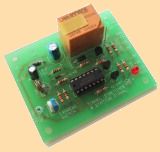
Tunnel Stretcher module
One common problem with model railways is the length of tunnels. Some
people will include tunnels just for the sake of it, their tunnels being
shorter than their trains! No amount of electronics will make such a
train set look any better. Bulldozing is the only solution.
However, if your tunnel is of a reasonable length, you will find this
circuit of great use. The train will vanish into the tunnel and wait a
predetermined time before emerging again. This delay is great for
stretching the scale "distance" between stations.
If we consider N scale as 1/160 scale, one scale kilometre is only 6.25
metres. I would be lucky if my layout has more than 12 metres of track
on it. Less than two miles!!
On timetable running days at some clubs, this lack of distance is
compensated for by running clocks four times as fast. However,
spectators would not be likely to appreciate this trick, taking things
exactly as they appeared. By putting a delay in my 3 metre long tunnel I
can stretch the scale journey out. It helps defeat the "train set" image
that short runs generate. Another thing that helps is the physical
layout of the tunnel itself. The entrance and exit of my tunnel are only
about 10cm apart, each in its own cutting. The track actually loops in
the tunnel. With the delay, it looks like a train heads south to a
station further down the line, returning later on the north bound line.
There is also another use to which this handy module can be put. You
will notice that it sports LED and lamp drivers so a two aspect signal
can be connected to it. If this signal is put at the end of a station
platform, along with the sensor and an isolated length of track, it
works as a station signal.
The signal will remain on red until a train comes up to it. The train
will stop because it has just come onto the length of isolated track
which is currently switched off by the relay in the tunnel stretcher
module. The train has also just covered the photo-transistor that is
mounted between the rails. This starts the delay. After the
predetermined time the signal will go green and the relay will close,
switching power to the isolated length of track. The train will then
move off again. A short while after it has cleared the photo-transistor,
the signal will revert to red and the relay will isolate the length of
track again, ready to stop the next train.
Some careful throttle work will be required if you don't want your train
to screech to a halt, only to take off like a startled rabbit several
seconds later. Of course, if the train is in a tunnel, it won't matter
because no one will be able to see it.
What if the train is a goods train or an express? You don't want that to
stop at a station. There is an override switch to allow for such trains.
It is appropriately labelled the "Express Switch" and closing it will
force the signal to green and hold the relay closed, ensuring that power
is switched through to the isolated stretch of track.
The Tunnel Stretcher and Station Signal Circuit
ABOUT THE CIRCUIT
In many ways this circuit is similar to the Signal Module project. It
has four similar circuit sections, though their arrangement is a little
different. Instead of two track sensors, only one is needed. Also, the
delay works in reverse to the one in the signal module. The gating is
somewhat simpler but the drivers are essentially the same though there
is one less of them, as no amber lamp is needed.
The sensor uses a MEL12 Darlington photo-transistor as the active
element. Light falling on the junction of the first transistor in the
Darlington pair has the same effect as applying a voltage to the base of
the device. It turns the transistor on. The degree of saturation, or how
hard the transistor pair is turned on, depends on the intensity of the
light.
Therefore when light is falling on the sensor, it will hold the input of
the Schmitt inverter IC1 :F LOW via R2. The output of IC1 :F will be
HIGH. When a train casts a shadow over the MEL12, the transistor will
not be turned on as hard, allowing its collector to be pulled up by R1
and RV1. When RV1 has been adjusted correctly, the voltage at this point
will rise over the input threshold of the Schmitt inverter IC1 :F and
its output will go LOW.
This sensor circuit behaves quite differently under various light
conditions. It is very sensitive under fluorescent lights, but under
incandescent lamps, it is harder to trip. If you find you have problems,
you may need to change R1 and R2. Reduce them if you can't make the
signals go GREEN, or increase them if the signals won't return to RED.
When you are making the adjustments, the delay can be disabled by
leaving C1 off the board or shortened by winding the 1M trim-pot fully
clockwise.
In some dark areas on your layout, you may find you need to mount a
street light so that some light falls on the sensor. Experimenters may
also like to try hiding infra red LEDs in overhead gantries or in
tunnels. Their light is not visible to the human eye.
When the output of IC1 :F is high, C1 will be held charged via R3 and
D1. The voltage will be above the upper threshold of IC1 :E, resulting
in a LOW at the output (pin 10) of IC1 :E. The signal is then inverted
again by IC1 :B, resulting in a HIGH being fed via R9 to Q3. This turns
on the RED LED. From this we can see an even number of inverters in
series will give a non inverted or "buffered" output. An odd number of
inverters in series will give an inverted output. There are three
inverters between C1 and the GREEN LED and relay drivers, resulting in
an inversion with respect to C1, so both of these will be off any time
the RED LED is on, and vice versa.
When a train causes a shadow to fall on the sensor, the output of IC1:F
goes LOW. C1 will discharge slowly through the 1M trim-pot and R3. When
the voltage on C1 falls below the lower threshold of IC1 :E, the GREEN
LED will be switched on and the relay will close, switching power
through to the track. This will allow the train to move off.
As soon as light falls on the sensor again, the output of IC1:F will go
HIGH again, charging C1 via R3 and D1, sending the signals back to RED
and opening the relay, isolating the track. The charging of C1 is a lot
faster than its discharging, making the time before power is removed
from the track rather short. Depending on the positioning of the sensor
and it's light source, you may find that the locomotive does not make it
off the isolated section of track
before the relay cuts power to it again. If this happens, the locomotive
will be stuck unless you hit the express switch. The solution is to
increase the time it takes to charge C1. This is done by increasing R3
to 100k or even higher if you find the time still not long enough.
Increasing R3 also stretches the length of time before the signal will
turn GREEN when a train arrives.
With the component values given, the maximum delay is about 20 seconds.
Increasing C1 to 22u will double this time.
The Express Switch works by shorting the input of IC1 :E to the 0V rail.
This forces the signal to GREEN and closes the relay. R4 is there to
prevent C1 from damaging the switch contacts by rapidly discharging
through them.
D2 provides protection for the module, should you accidentally connect
it to a supply backwards. C2 provides decoupling for the board. In other
words, it helps smooth fluctuations on the module's 12 volt rail caused
by parts of the circuit switching on or off.
The +12v symbol labeled "SOURCE" is
the common point for all the parts of the circuit that require 12 volts.
All other +12v symbols are connected to it. It is really a system much
like that used for the 0v or GROUND rail.
In some circuits you will notice that the GROUND symbol has been
replaced by a small triangle. This symbol represents a COMMON rail. It
is often used where the circuit's 0V rail is relative or in other words,
not actually at 0v but offset by another voltage.
BUILDING THE MODULE
The Tunnel Stretcher and Station Signal project is constructed on a
printed circuit board measuring 58mm by 73mm. There is ample space
between components, and the track and pad sizes are big enough to make
the beginner's job easier.
Start with the lower components first, working your way up to the
tallest. Don't mount the MEL12 photo-transistor on the board. It should
be connected to short flying leads, and pushed up through a hole between
the tracks.
Use a socket for the IC. The IC should be the last thing you install
before powering the board. Take care with orientation. If, when you
first power the board, you find nothing happens, check to make sure you
have remembered to put the chip in the socket. It may sound ridiculous,
but it is a very easy mistake to make.
The 10k trim-pot is for adjusting the sensitivity of the sensor. It is
mounted next to the pads to which the sensor is connected. The 1M
trim-pot is for adjusting the length of the delay.
Each driver has three outputs. One is for a grain of wheat lamp, one is
for a LED. The third is the LED on the PCB itself. These PCB mounted
LEDs make trouble shooting much easier. If you are working on the boards
under the layout, it saves you having to crawl out every time you need
to look at the signal. If the unit is being used in a tunnel, it is more
than likely that there won't be a signal to look at!
Again it is a good idea to use LEDs instead of lamps for the signals
themselves. If you do this, make sure that you common the anodes of the
LEDs (the long leads) and run the cathodes back to the driver outputs. A
wiring error to avoid is connecting a signal made with LEDs to the lamp
(LMP) output of the module. As there are no resistors in line with these
outputs, the LEDs would be destroyed instantly. Refer to the diagrams
and photographs in the Signals project.
A tri-colored LED can be easily used with this module. The common
cathode wire is connected to the zero volt rail of the PCB. The red and
green LEDs that the tri-colored LED houses are connected via 1k
resistors to pins 4 and 8 of the IC. The red LED goes to pin 4, the
green one to pin 8.
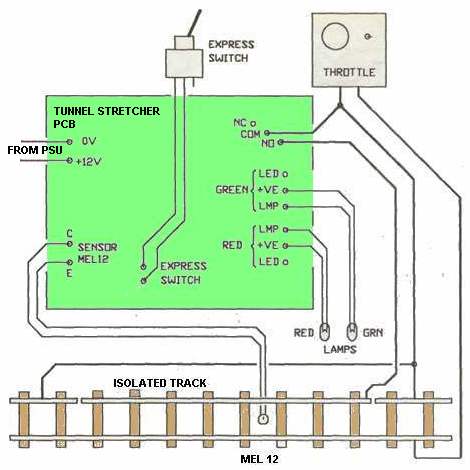
How to wire the Train Stretcher module to
the Throttle and track.
The MEL 12 photo-transistor, and how to mount it below the track
on your layout. On larger
scales, the hole can be
drilled between sleepers. With N scale track one
sleeper
may need to be removed. If you are careful with the positioning
of the hole, you may be able to get the active part of the
MEL 12 lined
up with the gap between the sleepers.
Be careful that stray ballast does
not fall down
the hole and cover the MEL 12.
PARTS
LIST |
|
4 - 330R 2 - 1k 1 - 2k2 3 - 4k7 1 - 10k 1 - 100k (see text) 1 - 10k mini trim pot 1 - 1M mini trim pot 1 - 10u 25v electro 1 - 100u25v electro 1 - 1N4148 2 - 1N4004 3 - BC547 1 - MEL12 1 - 40106 Hex Schmitt Inverter 1 - 3mm Green LED 1 - 3mm Red LED 1 - 12v SPDT RELAY 1 - 14 pin IC socket 1 - SPST toggle switch 1 - TUNNEL STRETCHER PCB |