|
ULTIMA MkII |
|
|
Encouraged by the popularity of all our
previous bugs, we have designed another FM transmitter, this time with a
range of 1km.
ULTIMA MkII circuit
The efficiency of this design is slightly higher than
our other designs as the
power consumption is about double and yet the Effective Radiated Power (ERP)
is about 4 times.
This is proved by the fact that the range is about twice, as it requires
4 times the power to double the range.
In this project we will cover some of the design features that make the
circuit so efficient. Basically it is the higher voltage but there are
also other contributing factors.
The way it works is this:
The minimum operating voltage for most transistor circuits is 1v, so a
1.5v supply will give a circuit about 100 metre range. At 3v it will
reach about 400 metres and at 6v it will reach about 1km. You will
recall the increased range of the Voyager was purely due to the 9v
supply and this time the 6v supply, as well as the tuned output, will
assist in providing the output power.
With any transmitting device, the primary requirement is range. To
achieve this, an efficient antenna system must be used and although a
dipole or loaded antenna provides a slight antenna gain, the usual
purpose for which this project is intended, makes a special antenna
impractical.
The main use for the Ultima is as an emergency beacon or signaling
device and in such a situation, the user may only have the branch of a
tree to throw the antenna over.
For this reason, and to keep the transmitter compact, a length of
hook-up wire about 1metre long is provided.
The advantage of transmitting on the FM band should be obvious as most
cars are now fitted with an FM receiver and they can be used to pick up
the transmission without the need for any special receiving equipment.
If a frequency was set aside at the lower end of the FM band for such a
purpose a safety channel could be set up at all types of outdoor centres
where the transmissions would not interfere with any commercial
operations as few if any FM stations are in remote areas.
Maybe something like this will be introduced in the near future. It's a
"catch 22" situation where you would have to use it illegally, to get it
approved nationally.
The Ultima project is built on a PC board 1.5cm x 7cm and can be fitted
into a variety of cases. The most appropriate will depend on the
intended use and if you want the project to be as small as possible, it
can be heat-shrunk and made virtually watertight.
FM transmission is highly efficient and a few milliwatts can get you a
long way. The clarity of FM, its lack of background noise and immunity
to electrical interference makes it ideal for faithfully monitoring all
types of sounds.
The impressive range of the UItima makes it ideal as a surveillance
device, for monitoring remote sheds and buildings, where the slightest
disturbance will be picked up and relayed to the monitoring point.
The Ultima is not intended as a hand-held microphone as frankly the
microphone sensitivity is too high and the circuit is not "tight" enough
to prevent the effect of stray capacitance of your body causing the
frequency to drift. See our handheld transmitter, the ANT, for this.
The main purpose of a transmitter is to get the greatest distance with the least current consumption.
To this end, the Ultima is the ultimate in design. It contains 3 novel features that have possibly never before been incorporated in the one design.
The front end is a simple common emitter stage with a gain of about 70-100, and decoupled from the battery via a 4k7 and 100n capacitor. These two components prevent motor-boating (instability) at low frequency.
There's another little known fact to be aware of, when designing the front end of a high gain amplifier such as this.
Since the electret microphone is an active device (it contains a FET), the gain of the FET must not be allowed to be too high, otherwise the front end will break into oscillation (sometimes called front-end squeal).
The gain is kept low by making the load resistor HIGH and that's why we have chosen 47k.
Coupling the audio to the RF oscillator is a 100n capacitor and this value is needed to pass the low audio frequencies.
The first of our "unusual" features is the 47k turn-on resistor on the base of the oscillator transistor.
After a great deal of experimenting we found a high value base resistor was sufficient to turn the transistor ON and produce a high amplitude waveform.
The oscillator circuit has been designed to oscillate at about 88MHz. The tuning capacitor in the oscillator is 47p and when the frequency is set, it remains set.
The Ultima is not a tunable bug and you should select a clear spot on the dial when setting it up, so that you don't interfere with any radio stations.
Apart from being illegal to transmit over a commercial station, you would have almost no chance of achieving any range if you were to do so.
The output of the oscillator is taken from the collector via a 10p.
The aim of the tapping is to pick off as much signal as possible without overloading the oscillator.
In technical terms we need a considerable amount of current to drive the output stage as gain is quite low (possibly about 5-20), depending on the quality of the transistor and the frequency of operation.
At 100MHz, the reactance of the 10p will be only about 200 ohms and that's why a small value such as this can be used.
The output stage has a number of features worth mentioning.
Firstly the emitter capacitor and resistor network may appear to be unnecessary as the stage is not a full bridge design. These components reduce the peak current and increase the input impedance of the output stage as seen by the oscillator stage. This improves and guarantees "start-up" of the circuit.
To get the greatest range from the Ultima, the output stage must be peaked and this is an essential part of the tuning and aligning. The tuned circuit in the output stage consists of a 5 turn coil and 47pF capacitor. The 8 turn coil is effectively an RFC (Radio Frequency Choke) to improve the matching of the output circuit to the antenna. The 1n capacitor on the RFC is designed to reduce harmonics and prevent interference on TV sets in the vicinity.
As output power is increased, the effect of harmonics becomes a real problem.
Shielding the project will have little effect as they are already appearing on the antenna and it's too late to suppress them once they get this far.
As we have said, one of the important stages in the construction is to peak the output. To do this, a simple POWER METER is required and its construction is also covered. The circuit attaches to a standard multimeter and uses the meter to give an indication of the signal strength. It also has a Light Emitting Diode that illuminates to give an indication of the relative power being emitted.
The illumination of the LED will give a valuable indication when peaking the circuit and will show how critical the values are at high frequency.
An on/off switch allows the project to be turned off when not required and the current consumption of our prototype was measured at 8mA, allowing a set of AA cells to last for about 150hours.
The 2N 3563 transistor in the output has been chosen as it gives the best performance at the least cost.
Surprisingly, a BC 547 will operate quite satisfactorily as an oscillator at 100MHz but provides very little gain at this frequency.
It only requires a gain greater than unity to function as an oscillator but in the output, a 2N 3563 provides a gain of between 5-20 and delivers the output we need.
No matter what other tricks you add to the output stage, you will not achieve better performance - for the same current.
The suggested maximum current for a 2N 3563 is 10-12-15mA (depending on the specification sheet you use), and only by decreasing the value of the bias resistor, does the output rise by a noticeable amount.
As you experiment with the circuit and peak it, you will see the changes in output power on the meter and/or the LED. But if range is increased at the expense of more current, you haven't improved the efficiency.
Our prototype produced 2v across the LED/resistor combination and the chip inside the LED could be seen to glow quite noticeably.
Not a great deal of weight can be put on this as a lot of RF energy is floating around the meter and will get into the movement to create a false reading.
But if you can see the LED glowing you know that energy MUST be present and that's why we have called it a LED POWER METER.
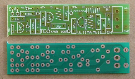
ASSEMBLY
A complete kit of components, including pre-wound coils and roll-tinned PC board is available from us and we hope you will buy more than one kit! Many readers buy two or more for their friends and some keep coming back for more!
The PC board is shown below.
THE LED POWER METER
Without exaggeration, it has taken hundreds of hours of experimenting
and at least 100 trips "around the block" to see how effective each
modification has been.
Sometimes an improvement via the power meter did not co-relate to an
improvement in range. You must always make a "field test" - it's the
only proof.
Although the circuit is not critical as such, a lot of work has gone
into the selection of each component and the layout of the board.
If you want your model to perform as good as ours, it is important to
use the exact same components and the same layout. That's why I suggest
you buy a kit.
It you are a seasoned hobbyist, and know what you are doing, you will
know the type of components to use. But if you are unsure or missing one
or two of the critical parts, don't take the chance, buy a kit.
I am not going to go through the finer points of placing the parts on
the board as we expect you will have made some of our other designs
already.
The coil winding details are below for those who wish to wind their own.
You can use slightly different gauge wire but the coil diameter and
spacing is critical.
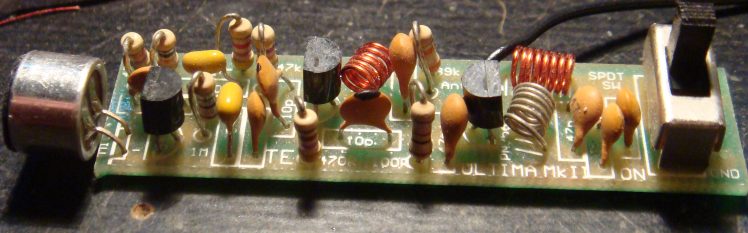
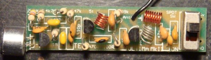
All the parts for the Ultima fit onto the board almost exactly as they
appear in the circuit diagram. This makes the circuit very easy to
follow and is one of the factors to good layout.
The coils are enamel coated and the enamel must be scraped off or
burn off before fitting them to the board. It is not satisfactory to
expect the enameling to burn off at the time when the coil is being
soldered in place.
All the components should be pressed firmly up to the board before
soldering. This also applies to the transistors. They should be pushed
down to the same height as the resistors as can be seen in the
photograph.
The PC board
contains a legend and the accompanying photos will show where everything
goes.
The next stage is tuning and peaking but before this can be carried out,
you will need to make up the LED POWER METER.
COIL WINDING
DETAILS:
1 - 5 turn tinned copper coil (.6mm wire) wound on a 3mm
diam screwdriver.
1 - 5 turn enamelled wire coil (.5mm wire) wound on a 3mm
diam screwdriver.
1 - 8
turn enamelled wire coil (.5mm wire) wound on a 3mm
diam screwdriver.
The turns are counted at the top of each loop. Five loops at
the top indicates a five turn coil etc.
The LED Power Meter
The LED
power Meter is a simple RF detector using diodes to charge a capacitor.
The voltage developed across the capacitor is indicated by a multimeter
set to a low voltage range. The circuit is soldered together without the
need for a PC board, as can be seen in the diagram above and paper clips
are used for the positive and negative terminals of the multimeter.
It will only take a few minutes to put this circuit together. The power
from the output of the Ultima is indicated by the illumination of
a LED and the voltage reading on the multimeter gives a further
indication of the output.
The reading is not calibrated and does not represent milliwatts output.
It is only a visual indication.
|
LED Power Meter Parts |
| 1 - 470R 1 - 100p ceramic 1 - 100n ceramic 2 - 1N 4148 diodes 1 - 5mm Red LED 1 - 2in (5cm) hook-up wire 2 - paper clips No PC board required |
USING THE LED POWER METER
To get the best performance out of this transmitter, an RF power meter
is used to maximize the output.
Since the output is very low, a conventional RF power meter cannot be
used. We need an RF milliwatt meter.
The circuit described in this section is very simple and uses a standard
multimeter to show the reading.
Across the input is a LED and resistor and the degree of brightness of
the LED, together with the voltage reading on the meter, gives an
indication of the energy level.
A digital multimeter may be used but the presence of RF may produce a
false reading.
Likewise, the radiated energy may upset some analogue meters and you may
get full scale deflection on the 15v range as well as the 250v range.
But the LED won't lie. It will accurately indicate the RF and you can
see the change in brightness as you adjust the coils in the output
stage.
Build the circuit for the LED Power Meter exactly as shown in the photo
and make sure the input lead is exactly 5mn long. If you keep to the
same layout as shown, your readings will closely coincide with ours.
When dealing with RF, lead length is very important and if the input
lead is longer, the meter will produce a lower reading.
The type of multimeter will also affect the reading and this is why we
cannot give a quantitative value for the output.
We don't have any means of providing a "standard" as we don't have any
bench-mark or reference point.
As soon as you build the power meter you will be able to test the
transmitter.
Connect the input lead to the antenna point
on the Ultima
board
(don't fit the antenna lead
yet) and switch on. Switch the multimeter to the 2v (or 2.5v or 5v)
range.
Keep the transmitter away from the meter to prevent the movement being
influenced by the RF and you should get a reading of about 2v.
The LED will glow quite noticeably and you can see the output on the LED
before the circuit is peaked.
Tune the radio across the band and there may be a number of spots where a signal is detected and it is
important to pick the fundamental.
The weaker side-tones have no range and this is where a tuning indicator
comes in. It will quickly indicate the fundamental frequency.
Move the radio away to confirm that the fundamental is being detected.
Or you cantune it to about 88.5MHz or somewhere at the low end of the
band and move the turns of the 5 turn oscillator coil either together or
stretch them apart until a feedback whistle is picked up by the radio.
This is the frequency of transmission.
When the turns are pushed together the frequency decreases and when
moved apart, the frequency increases.
You must not use any metal objects near the coil when moving the turns.
If you do, the reading will be upset.
The best item to use is a match or plastic knitting needle as you should
keep your fingers and hands away from the coil while adjusting it.
Now stretch or compress the 5 turns of the output TANK CIRCUIT so that
the reading on the POWER METER increases.
The multimeter will show a reading of about 2v and this voltage will
depend on getting the two sections of the circuit to operate at the same
frequency. Once you are satisfied the
project is working, remove the LED Power Meter and solder the antenna
lead to the board.
Move the radio a short distance away and tune across the band to make
sure the output is coming through and to see if you have picked up the
main frequency of transmission.
Carry out some experiments yourself and you will be very impressed with
the performance.
By moving the Ultima further away you will be able to pick up the sounds
it detects. Make sure the frequency of transmission is well away from
any radio stations as the signal from a station will swamp the Ultima when you are testing it for range.
If you want to change the frequency, you will have to set the frequency
of the oscillator section then adjust the output stage again, by using
Power Meter
If you do not get a squeal from the radio you can assume the frequency
is lower than the band (we have designed the output to be very close to
the bottom of the band) and it may be just a little too low.
In this case you will have to raise the frequency by expanding the turns
of the coil. This will bring the output onto the FM band.
To get the maximum range the antenna should be stretched out straight
and placed either horizontally or vertically. The receiving antenna must
be in the same plane to get the maximum range and both antennas should
be as high as possible.
The signal is generally not affected by brick walls, glass or plaster
but it will not pass through metal of any kind such as aluminium foil or
metal cladding. Trees can also have an effect due to the amount of
moisture they contain.
The signal will also find it difficult to get out of a car and you must
place the antenna near a window but away from the metal frame-work as
this will almost totally absorb the signal. The range from a car will be
a lot less than the 800m we stated at the beginning.
IF IT DOESN'T WORK
If you cannot detect an output on the LED
Power Meter, you can safely assume the oscillator stage is not working.
Measure the current for the project. It should be about 7mA. If it is
only about 3mA, the oscillator transistor may be damaged or not being
turned on.
You cannot measure any of the voltages around the oscillator transistor
and expect to get an accurate reading as the leads of a multimeter will
upset the operation of the circuit.
However if you measure the voltage on the emitter of the second
transistor and find it is zero, it is not being turned on and you should
check the 47k base-bias resistor. If it is 6v, the transistor may be
shorted or the 470R resistor may be open circuit.
But the most likely cause of the project not working will be a soldering
fault, such as a bridge between two tracks, poorly soldered joints, or
two components that have been swapped - such as the 47k and 470R.
The best thing to do is give the project to someone else to check as it
is very difficult to check your own work.
If you are picking up a blank spot (called the carrier) on the dial but
no audio, the fault will lie in the first stage or the microphone.
Check the voltage on the collector of the audio transistor. It should be
about 2.4v, however if it is above 5v or less than 1v, the transistor
will not be biased correctly and the 1M base-bias resistor may be at
fault.
The electret microphone needs only about 50mV across it to work and the
only real way to check it and the audio stage is to use a CRO or audio
amplifier (our prototype had 200mV DC across the microphone). By
whistling into the microphone at a distance of about one foot (30cm),
you will get an output of about 10 - 30mV. The audio transistor will
provide a gain of about 70 and produce an output of about 700mV -
2,100mV, as mentioned previously.
If the microphone does not produce at least 10mV, it may be around the
wrong way, damaged, or have very low sensitivity. Reducing the 68k load
resistor may help if the microphone is a low sensitivity type.
MODS
If you want to detune the transmitter to below 88MHz or run it at the
top end of the band, you will have to change the oscillator section as
well as the output section as they both determine the frequency.
To detune the transmitter to say 85-87MHz, you will need to add one turn
to both the oscillator coil and the tank coil, making them 6 turns.
To operate at 10BMHz, you will need to change both the 47p's in the
oscillator stage and tank circuit to 39p and follow the peaking
procedure described above.
IF IT DOESN'T WORK
Before you get involved in any technical problems, have someone check
the construction for dry joints, parts placement, shorts, and the like.
Nine times out of ten it's something simple.
Next check the current. It should be 8-10mA and any value outside this
will indicate a fault is present. Also check the voltage across the
power rails and the voltage across the front end (about 5v).
Next you must determine if the fault is in the audio section or the RF
section.
If the carrier is being produced you will get a blank spot on the dial
and the power LED will light up.
In this case the fault lies in the front end and can be due to the
microphone being around the wrong way, the audio transistor being
faulty, the 100n capacitor not passing the signal or one of a number of
faults.
Firstly check the voltage across the electret microphone. If it is
between .0.1v and 1v, the mic is drawing current and if you want to see
the output signal, you will need a CRO or mini amplifier.
A voltage of 2-3v on the collector of the audio transistor will indicate
it is biased correctly and any value outside this may mean the
transistor is faulty or has a gain above or below that expected.
In a self-biasing stage such as this, the gain of the transistor sets
the collector voltage and maximum amplification is achieved when the
collector is sitting at mid rail.
Two other components affecting the audio are the 22n and 100n
capacitors.
They may be damaged due to soldering and the only way to check them is
by bridging another capacitor across each or using a mini amplifier to
detect the audio.
If you have access to a CRO, you can observe the signal at each point in
the circuit and almost no fault will escape you. (Only the audio
section).
Replacing all the components is a last resort but may be necessary if
simple tests do not reveal the fault.
On the other hand, if no carrier is produced, the oscillator or output
stage will be at fault.
Firstly check the oscillator stage by removing the 47p capacitor from
the oscillator coil and connecting the input lead of the LED POWER METER
to the collector of the BC 547.
The meter should deflect slightly but the LED will not come on as it
requires at least 1.7v to be present before the LED will start to
illuminate.
The LED and resistor do not have to be removed as they do not impose any
load on the circuit until the voltage rises to above 1.7v.
If the meter does not deflect, the fault will lie in the oscillator
stage. The first component to change is the transistor, then the 10p
feedback capacitor.
Make sure the 39k turn-on resistor is providing a voltage to the base
of the oscillator transistor. It will be difficult to measure this
voltage accurately as the stage is producing RF and will upset the meter
reading.
Make sure the 470R has a voltage across it and this will indicate the
transistor is turned-on.
If the 47p capacitor has shorted the circuit will not oscillate. If these tests fail to locate
the fault, you should assemble another kit and come back to this one
later.
Reconnect the 47p and take the LED Power Meter to the antenna
connection.
NO deflection of the LED POWER METER can only mean one thing. The output
stage is not operating.
Firstly test the output transistor and make sure the voltages are
correct.
The enamel on the coils must be removed before soldering as it does not
conduct electricity at all.
Make sure the 39k provides a turn-on voltage and you can try shorting
across the 100R if you think this resistor is open.
A low RF output can be due to an open 22n capacitor across the battery,
the coils in the collector being spread too far apart or a faulty RF
transistor.
The only other possible explanation is damage to some of the components
during soldering.
For the cost of another kit, the quickest and easiest way is to start
again. You will take more care with the next construction and hopefully
things will work out successfully.
MOUNTING
The project can be mounted in a jiffy box that is large enough to take
the PC board and a battery holder. This will give it protection from the
weather etc if used in an outdoor situation.
If you want the project to be as small as possible, the PC board can be
heat-shrunk but you must be careful that the heat-shrinking does not
move the coils and change their frequency. Do not use a voltage higher
than 6v as the circuit is not designed for it and harmonics will be
produced that will interfere with TV reception.
I hope you find this project as interesting as we did. The range is most
impressive and it is incredible that such a low output will reach 1km.
|
|
|
26/11/2016